2001 CHRYSLER VOYAGER coolant
[x] Cancel search: coolantPage 1780 of 4284
CONDITION POSSIBLE CAUSES CORRECTION
4. Has undercoating been applied to
any unnecessary components?4. Clean undercoating as
necessary.
STEAM IS COMING FROM
FRONT OF VEHICLE
NEAR GRILL AREA WHEN
WEATHER IS WET,
ENGINE IS WARMED UP
AND RUNNING, AND
VEHICLE IS STATIONARY.
TEMPERATURE GAUGE
IS IN NORMAL RANGE1. During wet weather, moisture
(snow, ice, or rain condensation) on
the radiator will evaporate when the
thermostat opens. This opening
allows heated water into the radiator.
When the moisture contacts the hot
radiator, steam may be emitted. This
usually occurs in cold weather with
no fan or airflow to blow it away.1. Occasional steam emitting
from this area is normal. No
repair is necessary.
COOLANT ODOR 1. Coolant color is not necessarily an
indication of adequate corrosion or
temperature protection. Do not rely
on coolant color for determining
condition of coolant.1. Refer to Coolant in this group
for antifreeze tests. Adjust
antifreeze-to-water ratio as
necessary.
COOLANT LEVEL
CHANGES IN COOLANT
TANK. TEMPERATURE
GAUGE IS IN NORMAL
RANGE1. Level changes are to be expected
as coolant volume fluctuates with
engine temperature. If the level in
the tank was between the HOT and
COLD marks at normal engine
operating temperature, the level
should return to within that range
after operation at elevated
temperatures.1. This a normal condition. No
repair necessary.
DIAGNOSIS AND TESTING - COOLING SYSTEM
LEAK TEST
WARNING: THE WARNING WORDS ªDO NOT OPEN
HOTº ON THE RADIATOR PRESSURE CAP IS A
SAFETY PRECAUTION. WHEN HOT, PRESSURE
BUILDS UP IN COOLING SYSTEM. TO PREVENT
SCALDING OR INJURY, THE RADIATOR CAP
SHOULD NOT BE REMOVED WHILE THE SYSTEM
IS HOT OR UNDER PRESSURE.
With engine not running, remove pressure/vent cap
from the coolant recovery pressure container and
wipe the filler neck sealing seat clean. The coolant
recovery pressure container should be full.
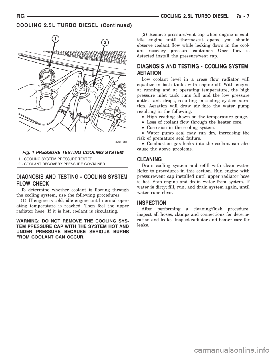
Attach the Cooling System Tester 7700 or equiva-
lent to the radiator, as shown in (Fig. 1) and apply
104 kPa (15 psi) pressure. If the pressure drops more
than 13.8 kPa (2 psi) in 2 minutes, inspect all points
for external leaks.
All radiator and heater hoses should be shaken
while at 104 kPa (15 psi), since some leaks occur only
while driving due to engine movement.
If there are no external leaks, after the gauge dial
shows a drop in pressure, detach the tester. Startengine and run until the thermostat opens, allowing
the coolant to expand. Reattach the cooling system
tester. If the needle on the dial fluctuates it indicates
a combustion leak, usually a head gasket leak.
WARNING: WITH TOOL IN PLACE, PRESSURE WILL
BUILD UP FAST. EXCESSIVE PRESSURE BUILT UP,
BY CONTINUOUS ENGINE OPERATION, MUST BE
RELEASED TO A SAFE PRESSURE POINT. NEVER
PERMIT PRESSURE TO EXCEED 138 kPa (20 psi).
If the needle on the dial does not fluctuate, raise
the engine rpm a few times. If an abnormal amount
of coolant or steam emits from the tailpipe, it may
indicate a coolant leak caused by a faulty head gas-
ket, cracked engine block, or cracked cylinder head.
There may be internal leaks that can be deter-
mined by removing the oil dipstick. If water globules
appear intermixed with the oil it will indicate an
internal leak in the engine. If there is an internal
leak, the engine must be disassembled for repair.
7a - 6 COOLING 2.5L TURBO DIESELRG
COOLING 2.5L TURBO DIESEL (Continued)
Page 1781 of 4284
DIAGNOSIS AND TESTING - COOLING SYSTEM
FLOW CHECK
To determine whether coolant is flowing through
the cooling system, use the following procedures:
(1) If engine is cold, idle engine until normal oper-
ating temperature is reached. Then feel the upper
radiator hose. If it is hot, coolant is circulating.
WARNING: DO NOT REMOVE THE COOLING SYS-
TEM PRESSURE CAP WITH THE SYSTEM HOT AND
UNDER PRESSURE BECAUSE SERIOUS BURNS
FROM COOLANT CAN OCCUR.(2) Remove pressure/vent cap when engine is cold,
idle engine until thermostat opens, you should
observe coolant flow while looking down in the cool-
ant recovery pressure container. Once flow is
detected install the pressure/vent cap.
DIAGNOSIS AND TESTING - COOLING SYSTEM
AERATION
Low coolant level in a cross flow radiator will
equalize in both tanks with engine off. With engine
at running and at operating temperature, the high
pressure inlet tank runs full and the low pressure
outlet tank drops, resulting in cooling system aera-
tion. Aeration will draw air into the water pump
resulting in the following:
²High reading shown on the temperature gauge.
²Loss of coolant flow through the heater core.
²Corrosion in the cooling system.
²Water pump seal may run dry, increasing the
risk of premature seal failure.
²Combustion gas leaks into the coolant can also
cause the above problems.
CLEANING
Drain cooling system and refill with clean water.
Refer to procedures in this section. Run engine with
pressure/vent cap installed until upper radiator hose
is hot. Stop engine and drain water from system. If
water is dirty; fill, run, and drain system again, until
water runs clear.
INSPECTION
After performing a cleaning/flush procedure,
inspect all hoses, clamps and connections for deterio-
ration and leaks. Inspect radiator and heater core for
leaks.
Fig. 1 PRESSURE TESTING COOLING SYSTEM
1 - COOLING SYSTEM PRESSURE TESTER
2 - COOLANT RECOVERY PRESSURE CONTAINER
RGCOOLING 2.5L TURBO DIESEL7a-7
COOLING 2.5L TURBO DIESEL (Continued)
Page 1788 of 4284
ENGINE
TABLE OF CONTENTS
page page
COOLANT
DESCRIPTION...........................14
DIAGNOSIS AND TESTING.................15
COOLANT CONCENTRATION TESTING......15
STANDARD PROCEDURE..................15
COOLANT SERVICE.....................15
ADDING ADDITIONAL COOLANT...........15
COOLANT LEVEL CHECK................16
REFILLING COOLING SYSTEM............16
DRAINING COOLING SYSTEM.............16
COOLANT RECOVERY PRESS CONTAINER
DESCRIPTION...........................17
OPERATION.............................17
REMOVAL..............................18
INSTALLATION...........................18
ENGINE COOLANT TEMP SENSOR
DESCRIPTION...........................19
OPERATION.............................19
REMOVAL..............................19
INSTALLATION...........................19
ENGINE COOLANT THERMOSTAT
DESCRIPTION...........................19
OPERATION.............................19
REMOVAL..............................19
INSTALLATION...........................20
RADIATOR
DESCRIPTION...........................20
OPERATION.............................20
REMOVAL..............................20
INSTALLATION...........................21
RADIATOR DRAINCOCK
REMOVAL..............................22INSTALLATION...........................22
WATER PUMP
DESCRIPTION...........................22
OPERATION.............................22
REMOVAL..............................22
CLEANING..............................23
INSTALLATION...........................23
RADIATOR PRESSURE CAP
DESCRIPTION...........................24
OPERATION.............................24
DIAGNOSIS AND TESTING.................25
COOLING SYSTEM PRESSURE CAP........25
PRESSURE RELIEF TEST................25
CLEANING..............................25
INSPECTION............................26
RADIATOR FAN
DESCRIPTION...........................26
OPERATION.............................26
DIAGNOSIS AND TESTING.................26
RADIATOR FAN MOTOR.................26
REMOVAL..............................27
INSTALLATION...........................27
HOSE CLAMPS
DESCRIPTION...........................27
OPERATION.............................28
RADIATOR FAN RELAY
DESCRIPTION...........................28
OPERATION.............................28
COOLANT SYSTEM HOSES
REMOVAL..............................28
INSTALLATION...........................29
COOLANT
DESCRIPTION
Coolant flows through the engine water jackets
and cylinder heads absorbing heat produced by the
engine during operation. The coolant carries heat to
the radiator and heater core. Here it is transferred to
ambient air passing through the radiator and heater
core fins.
The required ethylene-glycol (antifreeze) and water
mixture depends upon the climate and vehicle oper-
ating conditions. The recommended mixture of 50/50
ethylene-glycol and water will provide protectionagainst freezing to -37 deg. C (-35 deg. F). The anti-
freeze concentrationmust alwaysbe a minimum of
44 percent, year-round in all climates.If percentage
is lower than 44 percent, engine parts may be
eroded by cavitation, and cooling system com-
ponents may be severely damaged by corrosion.
Maximum protection against freezing is provided
with a 68 percent antifreeze concentration, which
prevents freezing down to -67.7 deg. C (-90 deg. F). A
higher percentage will freeze at a warmer tempera-
ture. Also, a higher percentage of antifreeze can
cause the engine to overheat because the specific
heat of antifreeze is lower than that of water.
7a - 14 ENGINERG
Page 1789 of 4284
100 Percent Ethylene-GlycolÐShould Not Be Used in
Chrysler Vehicles
Use of 100 percent ethylene-glycol will cause for-
mation of additive deposits in the system, as the cor-
rosion inhibitive additives in ethylene-glycol require
the presence of water to dissolve. The deposits act as
insulation, causing temperatures to rise to as high as
149 deg. C (300 deg. F). This temperature is hot
enough to melt plastic and soften solder. The
increased temperature can result in engine detona-
tion. In addition, 100 percent ethylene-glycol freezes
at -22 deg. C (-8 deg. F ).
Propylene-glycol FormulationsÐShould Not Be Used in
Chrysler Vehicles
Propylene-glycol formulations do not meet
Chrysler coolant specifications.It's overall effec-
tive temperature range is smaller than that of ethyl-
ene-glycol. The freeze point of 50/50 propylene-glycol
and water is -32 deg. C (-26 deg. F). 5 deg. C higher
than ethylene-glycol's freeze point. The boiling point
(protection against summer boil-over) of propylene-
glycol is 125 deg. C (257 deg.F)at96.5 kPa (14 psi),
compared to 128 deg. C (263 deg. F) for ethylene-gly-
col. Use of propylene-glycol can result in boil-over or
freeze-up in Chrysler vehicles, which are designed for
ethylene-glycol. Propylene glycol also has poorer heat
transfer characteristics than ethylene glycol. This
can increase cylinder head temperatures under cer-
tain conditions.
Propylene-glycol/Ethylene-glycol MixturesÐShould Not Be
Used in Chrysler Vehicles
Propylene-glycol/ethylene-glycol Mixtures can
cause the destabilization of various corrosion inhibi-
tors, causing damage to the various cooling system
components. Also, once ethylene-glycol and propy-
lene-glycol based coolants are mixed in the vehicle,
conventional methods of determining freeze point will
not be accurate. Both the refractive index and spe-
cific gravity differ between ethylene glycol and propy-
lene glycol.
CAUTION: Richer antifreeze mixtures cannot be
measured with normal field equipment and can
cause problems associated with 100 percent ethyl-
ene-glycol.DIAGNOSIS AND TESTING - COOLANT
CONCENTRATION TESTING
Coolant concentration should be checked when any
additional coolant was added to system or after a
coolant drain, flush and refill. The coolant mixture
offers optimum engine cooling and protection against
corrosion when mixed to a freeze point of -37ÉC
(-34ÉF) to -59ÉC (-50ÉF). The use of a hydrometer or a
refractometer can be used to test coolant concentra-
tion.
A hydrometer will test the amount of glycol in a
mixture by measuring the specific gravity of the mix-
ture. The higher the concentration of ethylene glycol,
the larger the number of balls that will float, and
higher the freeze protection (up to a maximum of
60% by volume glycol).
A refractometer will test the amount of glycol in a
coolant mixture by measuring the amount a beam of
light bends as it passes through the fluid.
Some coolant manufactures use other types of gly-
cols into their coolant formulations. Propylene glycol
is the most common new coolant. However, propylene
glycol based coolants do not provide the same freez-
ing protection and corrosion protection and is not rec-
ommended.
CAUTION: Do not mix types of coolantÐcorrosion
protection will be severely reduced.
STANDARD PROCEDURE - COOLANT SERVICE
For engine coolant recommended service schedule,
(Refer to LUBRICATION & MAINTENANCE/MAIN-
TENANCE SCHEDULES - DESCRIPTION).
STANDARD PROCEDURE - ADDING
ADDITIONAL COOLANT
The pressure/vent cap should not be removed
from the coolant recovery pressure container.
When additional coolant is needed to maintain this
level, it should be added to the coolant recovery pres-
sure container (Fig. 1). Use only 50/50 mix of ethyl-
ene glycol type antifreeze and distilled water. For the
recommeded antifreeze/coolant type (Refer to LUBRI-
CATION & MAINTENANCE/FLUID TYPES -
DESCRIPTION).
CAUTION: Do not use well water, or suspect water
supply in cooling system. A 50/50 ethylene glycol
and distilled water mix is recommended. For the
recommeded antifreeze/coolant type (Refer to
LUBRICATION & MAINTENANCE/FLUID TYPES -
DESCRIPTION).
RGENGINE7a-15
COOLANT (Continued)
Page 1790 of 4284
STANDARD PROCEDURE - COOLANT LEVEL
CHECK
NOTE: Do not remove pressure/vent cap for routine
coolant level inspections.
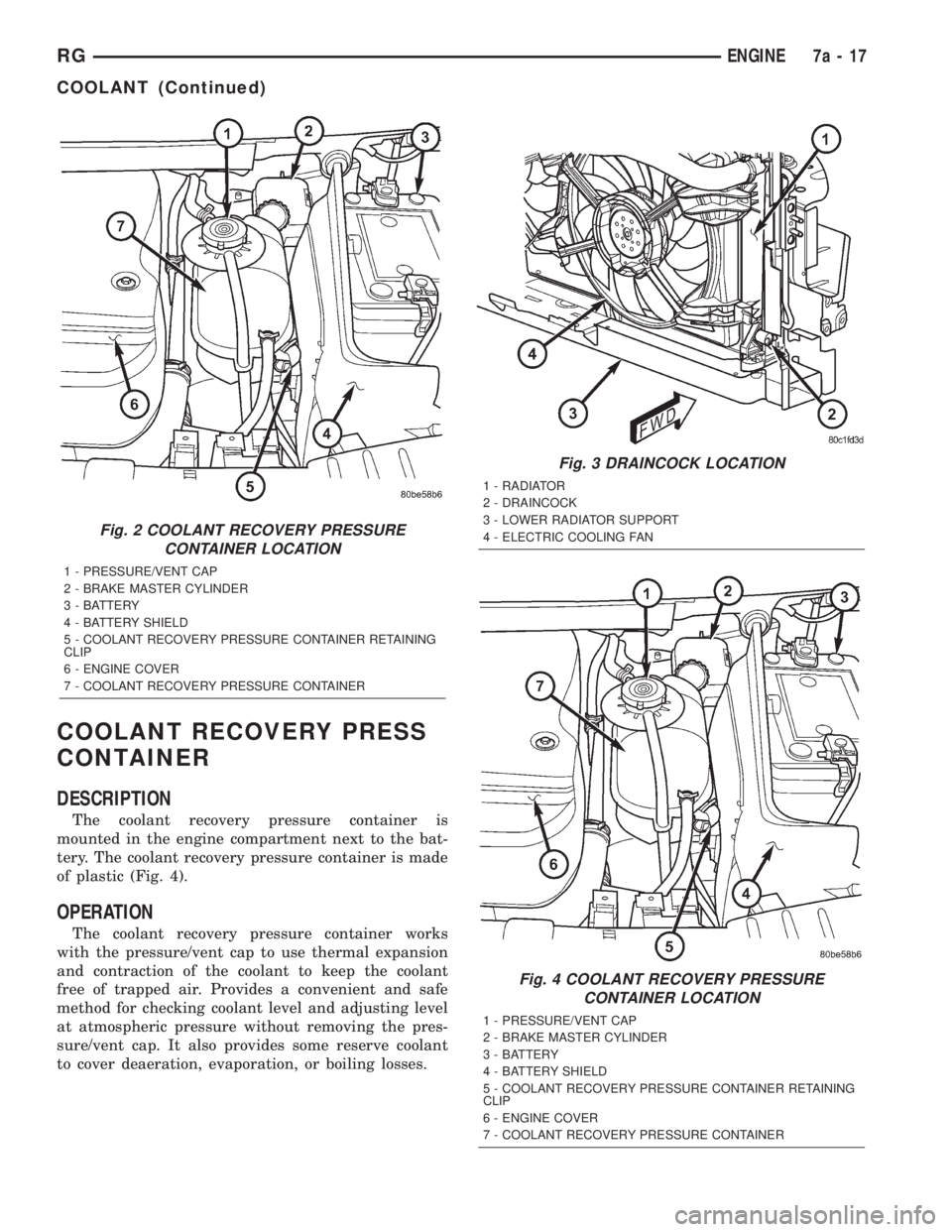
The coolant reserve system provides a quick visual
method for determining the coolant level without
removing the pressure/vent cap.With the engine
cold and not running,simply observe the level of
the coolant in the coolant recovery pressure container
(Fig. 2). The coolant level should be between the MIN
and MAX marks.
STANDARD PROCEDURE - REFILLING
COOLING SYSTEM
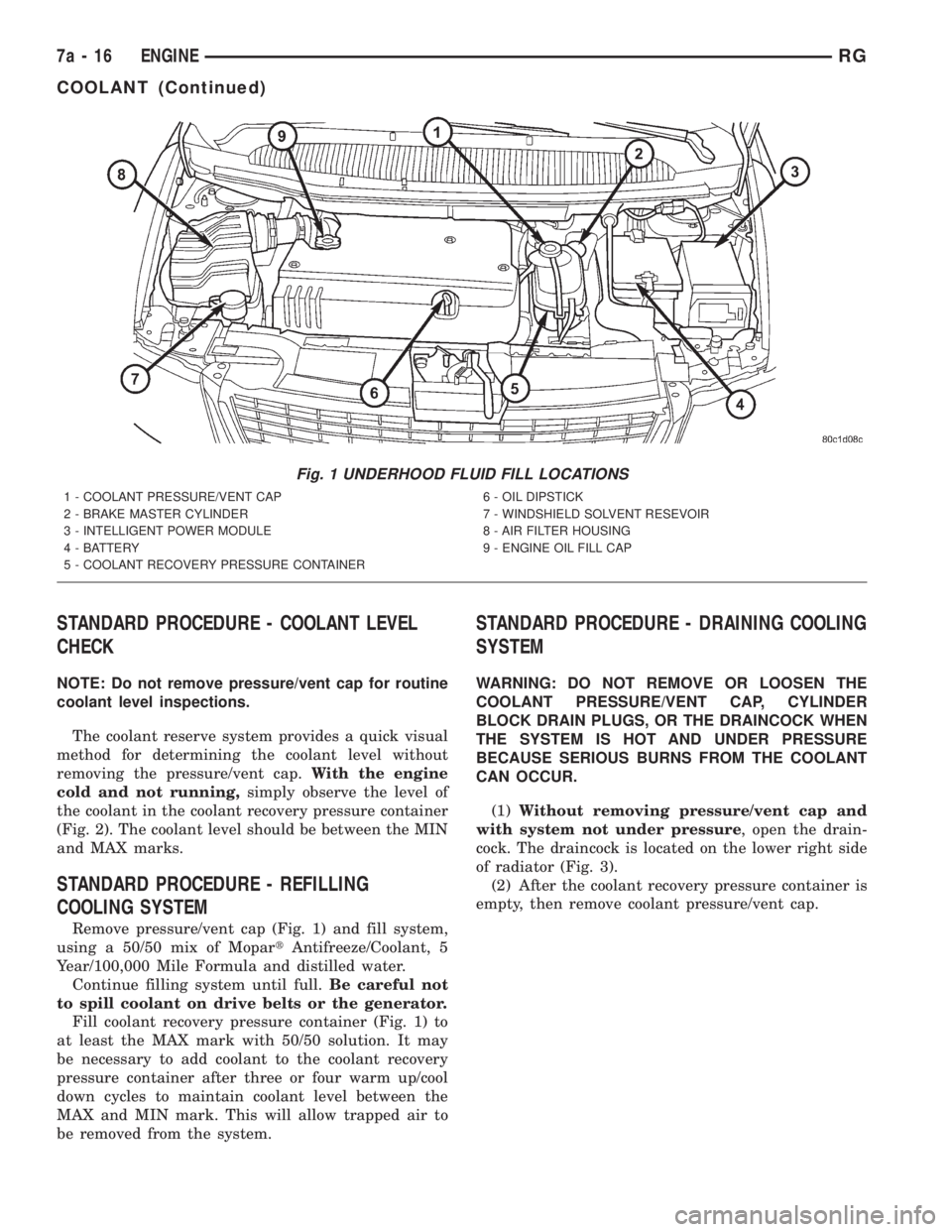
Remove pressure/vent cap (Fig. 1) and fill system,
using a 50/50 mix of MopartAntifreeze/Coolant, 5
Year/100,000 Mile Formula and distilled water.
Continue filling system until full.Be careful not
to spill coolant on drive belts or the generator.
Fill coolant recovery pressure container (Fig. 1) to
at least the MAX mark with 50/50 solution. It may
be necessary to add coolant to the coolant recovery
pressure container after three or four warm up/cool
down cycles to maintain coolant level between the
MAX and MIN mark. This will allow trapped air to
be removed from the system.
STANDARD PROCEDURE - DRAINING COOLING
SYSTEM
WARNING: DO NOT REMOVE OR LOOSEN THE
COOLANT PRESSURE/VENT CAP, CYLINDER
BLOCK DRAIN PLUGS, OR THE DRAINCOCK WHEN
THE SYSTEM IS HOT AND UNDER PRESSURE
BECAUSE SERIOUS BURNS FROM THE COOLANT
CAN OCCUR.
(1)Without removing pressure/vent cap and
with system not under pressure, open the drain-
cock. The draincock is located on the lower right side
of radiator (Fig. 3).
(2) After the coolant recovery pressure container is
empty, then remove coolant pressure/vent cap.
Fig. 1 UNDERHOOD FLUID FILL LOCATIONS
1 - COOLANT PRESSURE/VENT CAP
2 - BRAKE MASTER CYLINDER
3 - INTELLIGENT POWER MODULE
4 - BATTERY
5 - COOLANT RECOVERY PRESSURE CONTAINER6 - OIL DIPSTICK
7 - WINDSHIELD SOLVENT RESEVOIR
8 - AIR FILTER HOUSING
9 - ENGINE OIL FILL CAP
7a - 16 ENGINERG
COOLANT (Continued)
Page 1791 of 4284
COOLANT RECOVERY PRESS
CONTAINER
DESCRIPTION
The coolant recovery pressure container is
mounted in the engine compartment next to the bat-
tery. The coolant recovery pressure container is made
of plastic (Fig. 4).
OPERATION
The coolant recovery pressure container works
with the pressure/vent cap to use thermal expansion
and contraction of the coolant to keep the coolant
free of trapped air. Provides a convenient and safe
method for checking coolant level and adjusting level
at atmospheric pressure without removing the pres-
sure/vent cap. It also provides some reserve coolant
to cover deaeration, evaporation, or boiling losses.
Fig. 2 COOLANT RECOVERY PRESSURE
CONTAINER LOCATION
1 - PRESSURE/VENT CAP
2 - BRAKE MASTER CYLINDER
3 - BATTERY
4 - BATTERY SHIELD
5 - COOLANT RECOVERY PRESSURE CONTAINER RETAINING
CLIP
6 - ENGINE COVER
7 - COOLANT RECOVERY PRESSURE CONTAINER
Fig. 3 DRAINCOCK LOCATION
1 - RADIATOR
2 - DRAINCOCK
3 - LOWER RADIATOR SUPPORT
4 - ELECTRIC COOLING FAN
Fig. 4 COOLANT RECOVERY PRESSURE
CONTAINER LOCATION
1 - PRESSURE/VENT CAP
2 - BRAKE MASTER CYLINDER
3 - BATTERY
4 - BATTERY SHIELD
5 - COOLANT RECOVERY PRESSURE CONTAINER RETAINING
CLIP
6 - ENGINE COVER
7 - COOLANT RECOVERY PRESSURE CONTAINER
RGENGINE7a-17
COOLANT (Continued)
Page 1792 of 4284
REMOVAL
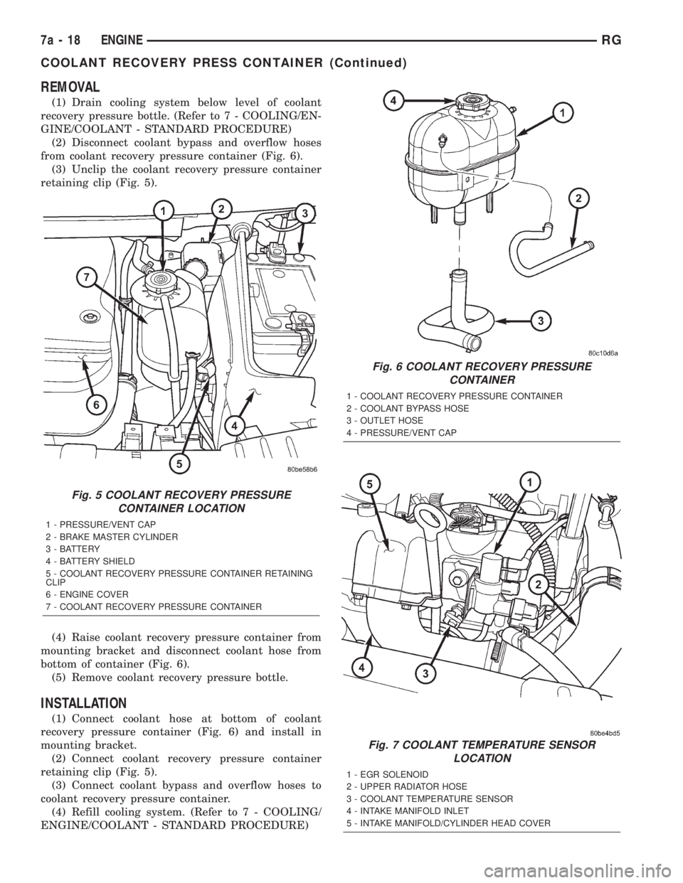
(1) Drain cooling system below level of coolant
recovery pressure bottle. (Refer to 7 - COOLING/EN-
GINE/COOLANT - STANDARD PROCEDURE)
(2) Disconnect coolant bypass and overflow hoses
from coolant recovery pressure container (Fig. 6).
(3) Unclip the coolant recovery pressure container
retaining clip (Fig. 5).
(4) Raise coolant recovery pressure container from
mounting bracket and disconnect coolant hose from
bottom of container (Fig. 6).
(5) Remove coolant recovery pressure bottle.
INSTALLATION
(1) Connect coolant hose at bottom of coolant
recovery pressure container (Fig. 6) and install in
mounting bracket.
(2) Connect coolant recovery pressure container
retaining clip (Fig. 5).
(3) Connect coolant bypass and overflow hoses to
coolant recovery pressure container.
(4) Refill cooling system. (Refer to 7 - COOLING/
ENGINE/COOLANT - STANDARD PROCEDURE)
Fig. 7 COOLANT TEMPERATURE SENSOR
LOCATION
1 - EGR SOLENOID
2 - UPPER RADIATOR HOSE
3 - COOLANT TEMPERATURE SENSOR
4 - INTAKE MANIFOLD INLET
5 - INTAKE MANIFOLD/CYLINDER HEAD COVER
Fig. 5 COOLANT RECOVERY PRESSURE
CONTAINER LOCATION
1 - PRESSURE/VENT CAP
2 - BRAKE MASTER CYLINDER
3 - BATTERY
4 - BATTERY SHIELD
5 - COOLANT RECOVERY PRESSURE CONTAINER RETAINING
CLIP
6 - ENGINE COVER
7 - COOLANT RECOVERY PRESSURE CONTAINER
Fig. 6 COOLANT RECOVERY PRESSURE
CONTAINER
1 - COOLANT RECOVERY PRESSURE CONTAINER
2 - COOLANT BYPASS HOSE
3 - OUTLET HOSE
4 - PRESSURE/VENT CAP
7a - 18 ENGINERG
COOLANT RECOVERY PRESS CONTAINER (Continued)
Page 1793 of 4284
ENGINE COOLANT TEMP
SENSOR
DESCRIPTION
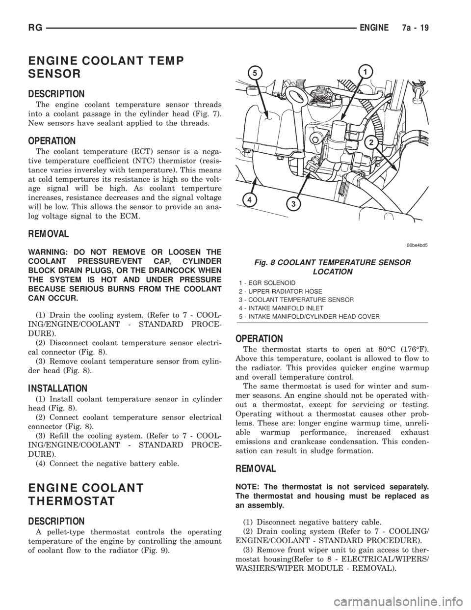
The engine coolant temperature sensor threads
into a coolant passage in the cylinder head (Fig. 7).
New sensors have sealant applied to the threads.
OPERATION
The coolant temperature (ECT) sensor is a nega-
tive temperature coefficient (NTC) thermistor (resis-
tance varies inversley with temperature). This means
at cold tempertures its resistance is high so the volt-
age signal will be high. As coolant temperture
increases, resistance decreases and the signal voltage
will be low. This allows the sensor to provide an ana-
log voltage signal to the ECM.
REMOVAL
WARNING: DO NOT REMOVE OR LOOSEN THE
COOLANT PRESSURE/VENT CAP, CYLINDER
BLOCK DRAIN PLUGS, OR THE DRAINCOCK WHEN
THE SYSTEM IS HOT AND UNDER PRESSURE
BECAUSE SERIOUS BURNS FROM THE COOLANT
CAN OCCUR.
(1) Drain the cooling system. (Refer to 7 - COOL-
ING/ENGINE/COOLANT - STANDARD PROCE-
DURE).
(2) Disconnect coolant temperature sensor electri-
cal connector (Fig. 8).
(3) Remove coolant temperature sensor from cylin-
der head (Fig. 8).
INSTALLATION
(1) Install coolant temperature sensor in cylinder
head (Fig. 8).
(2) Connect coolant temperature sensor electrical
connector (Fig. 8).
(3) Refill the cooling system. (Refer to 7 - COOL-
ING/ENGINE/COOLANT - STANDARD PROCE-
DURE).
(4) Connect the negative battery cable.
ENGINE COOLANT
THERMOSTAT
DESCRIPTION
A pellet-type thermostat controls the operating
temperature of the engine by controlling the amount
of coolant flow to the radiator (Fig. 9).
OPERATION
The thermostat starts to open at 80ÉC (176ÉF).
Above this temperature, coolant is allowed to flow to
the radiator. This provides quicker engine warmup
and overall temperature control.
The same thermostat is used for winter and sum-
mer seasons. An engine should not be operated with-
out a thermostat, except for servicing or testing.
Operating without a thermostat causes other prob-
lems. These are: longer engine warmup time, unreli-
able warmup performance, increased exhaust
emissions and crankcase condensation. This conden-
sation can result in sludge formation.
REMOVAL
NOTE: The thermostat is not serviced separately.
The thermostat and housing must be replaced as
an assembly.
(1) Disconnect negative battery cable.
(2) Drain cooling system (Refer to 7 - COOLING/
ENGINE/COOLANT - STANDARD PROCEDURE).
(3) Remove front wiper unit to gain access to ther-
mostat housing(Refer to 8 - ELECTRICAL/WIPERS/
WASHERS/WIPER MODULE - REMOVAL).
Fig. 8 COOLANT TEMPERATURE SENSOR
LOCATION
1 - EGR SOLENOID
2 - UPPER RADIATOR HOSE
3 - COOLANT TEMPERATURE SENSOR
4 - INTAKE MANIFOLD INLET
5 - INTAKE MANIFOLD/CYLINDER HEAD COVER
RGENGINE7a-19