Page 25 of 104
3-10
INSTRUMENT AND CONTROL FUNCTIONS
1
2
3
4
5
6
7
8
9
EW000130
w
Do not overfill the fuel tank. Avoid
spilling fuel on the hot engine. Do
not fill the fuel tank above the bot-
tom of the filler tube or it may
overflow when the fuel heats up
later and expands.
EAU00185
cC
Always wipe off spilled fuel imme-
diately with a dry and clean soft
cloth. Fuel may deteriorate painted
surfaces or plastic parts.
3 2
1
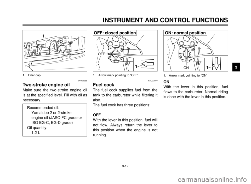
1. Filler tube
2. Filling nozzle
3. Fuel level
EAU01183
Fuel
(except for Switzerland and
Austria)
Make sure there is sufficient fuel in
the tank. Fill the fuel tank to the bot-
tom of the filler tube as shown in the
illustration.
EW000130
w
Do not overfill the fuel tank. Avoid
spilling fuel on the hot engine. Do
not fill the fuel tank above the bot-
tom of the filler tube or it may
overflow when the fuel heats up
later and expands.
2
1 3 4
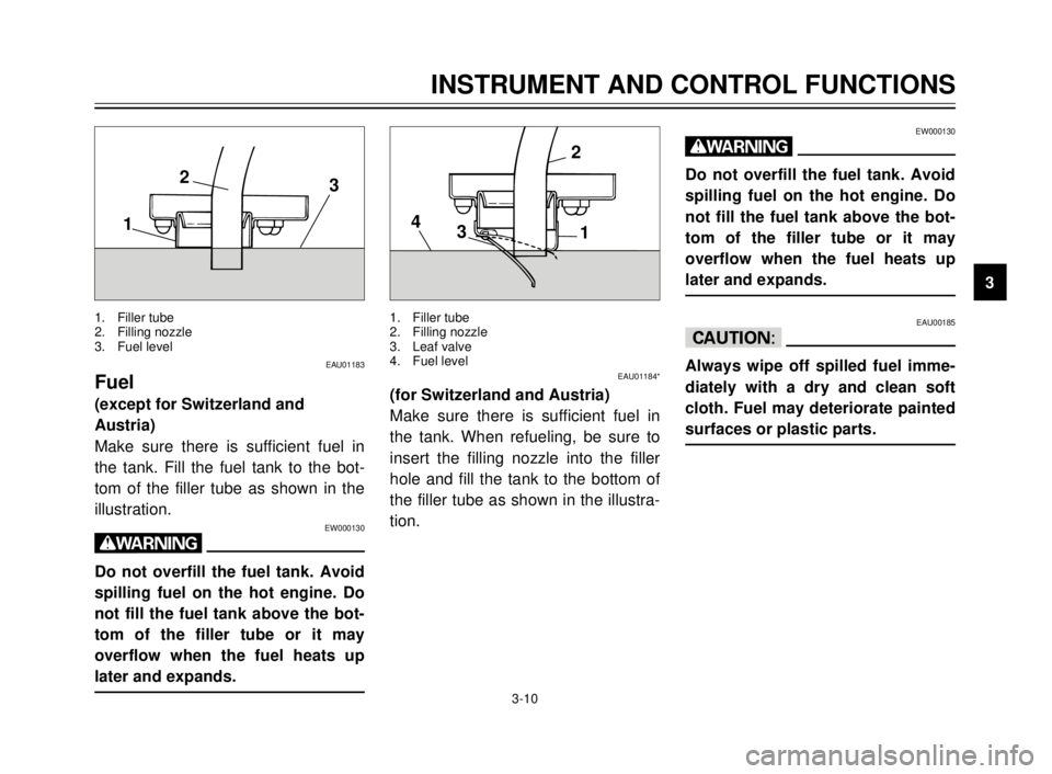
1. Filler tube
2. Filling nozzle
3. Leaf valve
4. Fuel level
EAU01184*
(for Switzerland and Austria)
Make sure there is sufficient fuel in
the tank. When refueling, be sure to
insert the filling nozzle into the filler
hole and fill the tank to the bottom of
the filler tube as shown in the illustra-
tion.
5AE-9-E3 (ENG) 4/11/0 11:06 AM Page 23
Page 26 of 104
3-11
INSTRUMENT AND CONTROL FUNCTIONS
1
2
3
4
5
6
7
8
9
EAU00191
NOTE:
If knocking or pinging occurs, use a
different brand of gasoline or higher
octane grade.
EAU01084
Catalyzer
(for Switzerland and Austria)
This motorcycle is equipped with a
catalytic converter in the exhaust
chamber.
EW000128
w
The exhaust system is hot during
and directly after engine operation.
Make sure the exhaust system has
cooled down before making any
adjustment to or lubricating the
motorcycle.
EC000114
cC
The following must be observed to
prevent a fire hazard or other dam-
ages.
8 8
Use only unleaded gasoline.
Use of leaded gasoline will
cause unrepairable damage to
the catalytic converter.
8 8
Never park this motorcycle in
an area that would cause a fire
hazard such as grass or other
materials that may easily burn.
8 8
Do not allow the engine to idle
for very long.Recommended fuel:
Regular unleaded gasoline
with a research octane
number of 91 or higher.
Fuel tank capacity:
Total:
11.0 L
Reserve:
2.2 L
5AE-9-E3 (ENG) 4/11/0 11:06 AM Page 24
Page 27 of 104
3-12
INSTRUMENT AND CONTROL FUNCTIONS
1
2
3
4
5
6
7
8
9ON1
1. Arrow mark pointing to “ON”
EAU03050
Fuel cock
The fuel cock supplies fuel from the
tank to the carburetor while filtering it
also.
The fuel cock has three positions:
OFF
With the lever in this position, fuel will
not flow. Always return the lever to
this position when the engine is not
running.ON
With the lever in this position, fuel
flows to the carburetor. Normal riding
is done with the lever in this position.
1
OFF
1. Arrow mark pointing to “OFF”
EAU02956
Two-stroke engine oil
Make sure the two-stroke engine oil
is at the specified level. Fill with oil as
necessary.
1
1. Filler cap
Recommended oil:
Yamalube 2 or 2-stroke
engine oil (JASO FC grade or
ISO EG-C, EG-D grade)
Oil quantity:
1.2 L
OFF: closed positionON: normal position
5AE-9-E3 (ENG) 4/11/0 11:06 AM Page 25
Page 28 of 104
1
a
b1
RES
This indicates reserve. If you run out
of fuel while riding, move the lever to
this position. Fill the tank at the first
opportunity. Be sure to set the lever
back to “ON” after refueling!EAU02976
Starter (choke) “1”
Starting a cold engine requires a rich-
er air-fuel mixture. A separate starter
circuit supplies this mixture.
Move in direction ato turn on the
starter (choke).
Move in direction bto turn off the
starter (choke).
EAU01619Seat
To remove
Insert the key into the lock and turn it
clockwise.
1. Starter(choke) “1” 1. Unlock
3-13
INSTRUMENT AND CONTROL FUNCTIONS
1
2
3
4
5
6
7
8
9
1
RES
1. Arrow mark pointing to “RES”
RES: reserve position
5AE-9-E3 (ENG) 4/11/0 11:06 AM Page 26
Page 29 of 104

3-14
INSTRUMENT AND CONTROL FUNCTIONS
1
2
3
4
5
6
7
8
9
EAU00260Helmet holder
To open the helmet holder, insert the
key in the lock and turn it as shown.
To lock the helmet holder, replace
the holder in its original position.
EW000030
w
Never ride with a helmet in the hel-
met holder. The helmet may hit
objects, causing loss of control
and possibly an accident.
EAU00295
Rear shock absorber
adjustment
This shock absorber is equipped with
a spring preload adjusting ring.
Adjust spring preload as follows.
Turn the adjusting ring in direction a
to increase spring preload and in
direction bto decrease spring pre-
load.
Make sure that the appropriate notch
in the adjusting ring is aligned with
the position indicator on the rear
shock absorber. To install
Insert the projection on the front of
the seat into the seat holder. Push
down on the seat and remove the
key.
NOTE:
Make sure that the seat is securely
fitted.
1
2
1. Projection
2. Seat holder
1
1. Open
a
b1
1. Adjusting ring
5AE-9-E3 (ENG) 4/11/0 11:06 AM Page 27
Page 30 of 104
3-15
1
2
3
4
5
6
7
8
9
1
2
1
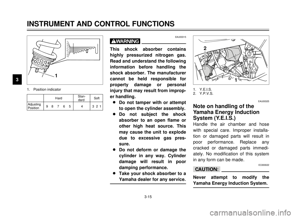
1. Position indicator1. Y.E.I.S.
2. Y.P.V.S.
EAU00315
w
This shock absorber contains
highly pressurized nitrogen gas.
Read and understand the following
information before handling the
shock absorber. The manufacturer
cannot be held responsible for
property damage or personal
injury that may result from improp-
er handling.
8 8
Do not tamper with or attempt
to open the cylinder assembly.
8 8
Do not subject the shock
absorber to an open flame or
other high heat source. This
may cause the unit to explode
due to excessive gas pres-
sure.
8 8
Do not deform or damage the
cylinder in any way. Cylinder
damage will result in poor
damping performance.
8 8
Take your shock absorber to a
Yamaha dealer for any service.
EAU00325
Note on handling of the
Yamaha Energy Induction
System (Y.E.I.S.)
Handle the air chamber and hose
with special care. Improper installa-
tion or damaged parts will result in
poor performance. Replace any
cracked or damaged parts immedi-
ately. No modification of this system
in any form can be made.
EC000022
cC
Never attempt to modify the
Yamaha Energy Induction System.
INSTRUMENT AND CONTROL FUNCTIONS
1
2
3
4
5
6
7
8
9
HardStan-
Softdard
Adjusting
98 7 6 5 4 321
Position
5AE-9-E3 (ENG) 4/11/0 11:06 AM Page 28
Page 31 of 104
3-16
EAU00326
Y.P.V.S. (Yamaha Power Valve
System)
The Y.P.V.S. is a vital part of the
engine and requires very sophisticat-
ed adjustment. Adjustment should be
left to a Yamaha dealer who has the
professional knowledge and experi-
ence to do so.
EC000023
cC
The Y.P.V.S. was set at the
Yamaha factory after many tests. If
the settings are disturbed by
someone without sufficient techni-
cal knowledge, poor engine perfor-
mance and damage may result.
The Y.P.V.S. operation can be heard
in the following instances:
8When the main switch is turned
on and the engine is started.
8When the engine stalls while the
main switch is on.
EC000024
cC
If the Y.P.V.S. does not operate,
ask a Yamaha dealer to inspect the
vehicle.
EAU00330Sidestand
This model is equipped with an igni-
tion circuit cut-off system. The motor-
cycle must not be ridden when the
sidestand is down. The sidestand is
located on the left side of the frame.
(Refer to page 5-1 for an explanation
of this system.)
INSTRUMENT AND CONTROL FUNCTIONS
1
2
3
4
5
6
7
8
9
5AE-9-E3 (ENG) 4/11/0 11:06 AM Page 29
Page 32 of 104

3-17
EW000044
w
This motorcycle must not be oper-
ated with the sidestand in the
down position. If the stand is not
properly retracted, it could contact
the ground and distract the opera-
tor, resulting in a possible loss of
control. Yamaha has designed into
this motorcycle a lockout system
to assist the operator in fulfilling
the responsibility of retracting the
sidestand. Please check carefully
the operating instructions listed
below and if there is any indication
of a malfunction, return the motor-
cycle to a Yamaha dealer immedi-
ately for repair.
EAU00331
Sidestand/clutch switch
operation check
Check the operation of the sidestand
switch and clutch switch against the
information below.
EW000045
w
If improper operation is noted,
consult a Yamaha dealer immedi-
ately.
INSTRUMENT AND CONTROL FUNCTIONS
1
2
3
4
5
6
7
8
9TURN THE MAIN SWITCH TO “ON” AND
THE ENGINE STOP SWITCH TO “#”.
TRANSMISSION IS IN GEAR AND
SIDESTAND IS UP.
PULL IN CLUTCH LEVER AND
PUSH THE START SWITCH.
ENGINE WILL START.
CLUTCH SWITCH IS OK.
SIDESTAND IS DOWN.
ENGINE WILL STALL.
SIDESTAND SWITCH IS OK.
5AE-9-E3 (ENG) 4/11/0 11:06 AM Page 30
 1
1 2
2 3
3 4
4 5
5 6
6 7
7 8
8 9
9 10
10 11
11 12
12 13
13 14
14 15
15 16
16 17
17 18
18 19
19 20
20 21
21 22
22 23
23 24
24 25
25 26
26 27
27 28
28 29
29 30
30 31
31 32
32 33
33 34
34 35
35 36
36 37
37 38
38 39
39 40
40 41
41 42
42 43
43 44
44 45
45 46
46 47
47 48
48 49
49 50
50 51
51 52
52 53
53 54
54 55
55 56
56 57
57 58
58 59
59 60
60 61
61 62
62 63
63 64
64 65
65 66
66 67
67 68
68 69
69 70
70 71
71 72
72 73
73 74
74 75
75 76
76 77
77 78
78 79
79 80
80 81
81 82
82 83
83 84
84 85
85 86
86 87
87 88
88 89
89 90
90 91
91 92
92 93
93 94
94 95
95 96
96 97
97 98
98 99
99 100
100 101
101 102
102 103
103

