Page 15 of 104

INSTRUMENT AND CONTROL FUNCTIONS
Main switch/steering lock........................................3-1
Indicator lights ........................................................3-2
Oil level indicator circuit check ...............................3-3
Speedometer ..........................................................3-4
Tachometer ............................................................3-4
Engine temperature gauge .....................................3-5
Handlebar switches ................................................3-5
Headlight beam variation ........................................3-6
Clutch lever.............................................................3-8
Shift pedal...............................................................3-8
Front brake lever ....................................................3-8
Rear brake pedal ....................................................3-9
Fuel tank cap ..........................................................3-9
Fuel.......................................................................3-10
Catalyzer (for Switzerland and Austria) ................3-11
Two-stroke engine oil ...........................................3-12
Fuel cock ..............................................................3-12
Starter (choke) “1” ..............................................3-13
Seat ......................................................................3-13
Helmet holder .......................................................3-14
Rear shock absorber adjustment..........................3-14
Note on handling of the Yamaha Energy
Induction System (Y.E.I.S.) ..................................3-15Y.P.V.S. (Yamaha Power Valve System) .............3-16
Sidestand..............................................................3-16
Sidestand/clutch switch operation check ..............3-17
3
5AE-9-E3 (ENG) 4/11/0 11:06 AM Page 13
Page 29 of 104

3-14
INSTRUMENT AND CONTROL FUNCTIONS
1
2
3
4
5
6
7
8
9
EAU00260Helmet holder
To open the helmet holder, insert the
key in the lock and turn it as shown.
To lock the helmet holder, replace
the holder in its original position.
EW000030
w
Never ride with a helmet in the hel-
met holder. The helmet may hit
objects, causing loss of control
and possibly an accident.
EAU00295
Rear shock absorber
adjustment
This shock absorber is equipped with
a spring preload adjusting ring.
Adjust spring preload as follows.
Turn the adjusting ring in direction a
to increase spring preload and in
direction bto decrease spring pre-
load.
Make sure that the appropriate notch
in the adjusting ring is aligned with
the position indicator on the rear
shock absorber. To install
Insert the projection on the front of
the seat into the seat holder. Push
down on the seat and remove the
key.
NOTE:
Make sure that the seat is securely
fitted.
1
2
1. Projection
2. Seat holder
1
1. Open
a
b1
1. Adjusting ring
5AE-9-E3 (ENG) 4/11/0 11:06 AM Page 27
Page 60 of 104

6-15
PERIODIC MAINTENANCE AND MINOR REPAIR
1
2
3
4
5
6
7
8
9
EC000082
cC
8
8
Make sure the air filter is prop-
erly seated in the air filter
case.
8 8
The engine should never be
run without the air filter
installed. Excessive piston
and/or cylinder wear may
result.
EW000131
w
Make sure that the fuel hoses and
vacuum hose are properly con-
nected, in place and not pinched. If
a hose is damaged, be sure to
replace it.
EAU00629Carburetor adjustment
The carburetor is a vital part of the
engine and requires very sophisticat-
ed adjustment. Most adjustments
should be left to a Yamaha dealer
who has the professional knowledge
and experience to do so. However,
the following may be serviced by the
owner as part of routine mainte-
nance.
EC000094
cC
The carburetor was set at the
Yamaha factory after many tests. If
the settings are changed, poor
engine performance and damage
may result.
ba
1
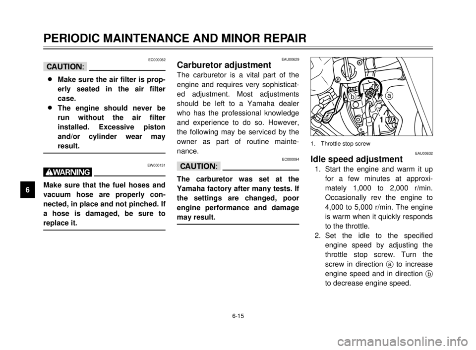
EAU00632Idle speed adjustment
1. Start the engine and warm it up
for a few minutes at approxi-
mately 1,000 to 2,000 r/min.
Occasionally rev the engine to
4,000 to 5,000 r/min. The engine
is warm when it quickly responds
to the throttle.
2. Set the idle to the specified
engine speed by adjusting the
throttle stop screw. Turn the
screw in direction ato increase
engine speed and in direction b
to decrease engine speed.
1. Throttle stop screw
5AE-9-E3 (ENG) 4/11/0 11:06 AM Page 58
Page 101 of 104

INDEX
Recommended shift points
(for Switzerland only) ............................5-5
Right view ................................................2-2
S
Seat .......................................................3-13
Shift pedal ...............................................3-8
Shifting ....................................................5-4
Sidestand ..............................................3-16
Sidestand lubrication .............................6-27
Sidestand/clutch switch operation
check ..................................................3-17
Spark plug inspection ..............................6-8
Specifications ..........................................8-1
Speedometer ...........................................3-4
Start switch ..............................................3-7
Starter (choke) “1” ...............................3-13
Starting a warm engine ...........................5-4
Starting the engine ..................................5-1
Steering inspection ................................6-28
Storage ....................................................7-4
T
Tachometer .............................................3-4
Taillight bulb replacement .....................6-32
Throttle cable and grip lubrication .........6-25
Throttle cable free play adjustment .......6-16
Tips for reducing fuel consumption .........5-5
Tires ......................................................6-17
Tool kit .....................................................6-1
Transmission oil ......................................6-9
Troubleshooting.....................................6-36
Troubleshooting chart............................6-37
Turn indicator light ...................................3-2
Turn signal light bulb replacement ........6-32Turn signal switch....................................3-5
Two-stroke engine oil ............................3-12
V
Vehicle identification number ..................9-1
W
Wheel bearings .....................................6-29
Wheels ..................................................6-19
Y
Y.P.V.S.
(Yamaha Power Valve System) ..........3-16
5AE-9-E3 (ENG) 4/11/0 11:06 AM Page 99