Page 1784 of 4770
TORQUE CONVERTER CLUTCH AND DRIVE PLATE
1919 Author�: Date�:
TORQUE CONVERTER CLUTCH
AND DRIVE PLATE
INSPECTI")
AT0953
SST
AX03J±01
AT3306
Hold
TurnLock
Free
Q04237
AX±26
± AUTOMATIC TRANSAXLE (A140E)TORQUE CONVERTER CLUTCH AND DRIVE PLATE
1919 Author�: Date�:
TORQUE CONVERTER CLUTCH
AND DRIVE PLATE
INSPECTION
1. INSPECT ONE±WAY CLUTCH
(a) Install SST into the inner race of the one±way clutch.
SST 09350±32014 (09351±32010)
(b) Install SST so that it fits in the notch of the converter hub
and outer race of the one±way clutch.
SST 09350±32014 (09351±32020)
(c) With the torque converter clutch standing on its side,the
clutch locks when turned counterclockwise, and rotates
freely and smoothly clockwise.
If necessary, clean the converter and retest the clutch. Replace
the converter clutch if the clutch still fails the test.
2. MEASURE DRIVE PLATE RUNOUT AND INSPECT
RING GEAR
Set up a dial indicator and measure the drive plate runout.
Maximum runout: 0.20 mm (0.0079 in.)
If the runout is not within the specification or if the ring gear is
damaged, replace the drive plate. If installing a new drive plate,
note the orientation of spacers and tighten the bolts.
Torque: 83 N´m (850 kgf´cm, 61 ft´lbf)
Page 1836 of 4770
AUTOMATIC TRANSAXLEOIL PUMP ±
AX±40
2. INSTALL DRIVEN GEAR AND DRIVE GEAR
Make sure the top of the gears are facing upward.
3. INSTALL STATOR SHAFT TO PUMP BODY
(a) Align the stator shaft with each bolt hole.
(b) Torque the 11 bolts.
Torque: 10 N´m (100 kgf´cm, 7 ft´lbf)
4. INSTALL THRUST WASHER
(a) Coat the thrust washer with petroleum jelly.
(b) Align the tab of the washer with the hollow of the pump
body.
5. INSTALL OIL SEAL RINGS
Install the 2 oil seal rings to the stator shaft back side.
NOTICE: Do not spread the ring ends more than necessary.
HINT: After installing the oil seal rings, check that they
move smoothly.
6. CHECK PUMP DRIVE GEAR ROTATION
Turn the drive gear with 2 screwdrivers and make sure it
rotates smoothly.
NOTICE: Be careful not to damage the oil seal lip.
Page 1843 of 4770
AUTOMATIC TRANSAXLEFORWARD CLUTCH ±
AX±47
(b) Remove the 2 O±rings from the piston.
6. IF NECESSARY, REMOVE OIL SEAL RINGS
Remove the 3 oil seal rings from the shaft.
FORWARD CLUTCH INSPECTION
1. INSPECT CLUTCH PISTON
(a) Check that the check ball is free by shaking the piston.
(b) Check that the valve does not leak by applying low±pres-
sure compressed air.
2. INSPECT DISCS, PLATES AND FLANGE
Check if the sliding surfaces of the discs, plates and
flange are worn or burnt. If necessary, replace them.
HINT:
�If the lining of the disc is peeling off or discolored, or
even if a part of the printed numbers are defaced, re-
place all discs.
�Before assembling new discs, soak them in ATF for
at least 15 minutes.
FORWARD CLUTCH ASSEMBLY
1. INSTALL OIL SEAL RINGS
Install the 3 oil seal rings to the shaft.
NOTICE: Do not spread the ring ends more than necessary.
HINT: After installing the oil seal rings, check that they
move smoothly.
AX038±03
AX039±04
Page 1870 of 4770
AUTOMATIC TRANSAXLEOVERDRIVE UNIT ±
AX±74
2. REMOVE OIL SEAL RINGS
OVERDRIVE CASE ASSEMBLY
1. INSTALL OIL SEAL RINGS ON OVERDRIVE CASE
Install the 2 oil seal rings to the overdrive case groove,
then snug them down by squeezing their ends together.
HINT: After installing the oil seal rings, check that they
move smoothly.
2. INSTALL C0 ACCUMULATOR PISTON TO OVER-
DRIVE CASE
(a) Install a new O±ring to the accumulator piston.
(b) Coat the O±ring with ATF.
(c) Install the accumulator piston, 2 springs and retaining
plate.
(d) Using snap ring pliers, install the snap ring.
AX042±02
Page 1912 of 4770
AUTOMATIC TRANSAXLECOMPONENT PARTS INSTALLATION ±
AX±116
17. INSTALL NEW SECOND BRAKE GASKET
Install a new gasket until it makes contact with the second
brake drum.
18. CHECK OPERATION OF SECOND BRAKE
Apply compressed air into the second brake gasket and
confirm that the piston moves.
19. INSTALL SUN GEAR AND SUN GEAR INPUT DRUM
(a) Coat the thrust washer with petroleum jelly and install it
on the sun gear input drum.
(b) While turning the sun gear clockwise, install it into the
No.1 one±way clutch.
20. INSTALL OIL SEAL RING TO INTERMEDIATE SHAFT
HINT: After installing the oil seal ring, check that it moves
smoothly.
Page 2007 of 4770
N22592
N20984
N15432
20 mm
(0.79 in.)
BO±48
± BODYWINDSHIELD
2396 Author�: Date�:
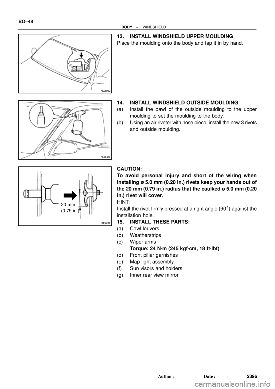
13. INSTALL WINDSHIELD UPPER MOULDING
Place the moulding onto the body and tap it in by hand.
14. INSTALL WINDSHIELD OUTSIDE MOULDING
(a) Install the pawl of the outside moulding to the upper
moulding to set the moulding to the body.
(b) Using an air riveter with nose piece, install the new 3 rivets
and outside moulding.
CAUTION:
To avoid personal injury and short of the wiring when
installing ù 5.0 mm (0.20 in.) rivets keep your hands out of
the 20 mm (0.79 in.) radius that the caulked ù 5.0 mm (0.20
in.) rivet will cover.
HINT:
Install the rivet firmly pressed at a right angle (90°) against the
installation hole.
15. INSTALL THESE PARTS:
(a) Cowl louvers
(b) Weatherstrips
(c) Wiper arms
Torque: 24 N´m (245 kgf´cm, 18 ft´lbf)
(d) Front pillar garnishes
(e) Map light assembly
(f) Sun visors and holders
(g) Inner rear view mirror
Page 2027 of 4770

Gear Pointer (Brown)
H01818
H01819
H01820
Parts shown
disassembled
for clarity BO±68
± BODYSLIDING ROOF (TMMK Made)
2416 Author�: Date�:
ADJUSTMENT
1. A")
BO0LY±01
H01817
Motor Housing
Pointer (Grey)
Gear Pointer (Brown)
H01818
H01819
H01820
Parts shown
disassembled
for clarity BO±68
± BODYSLIDING ROOF (TMMK Made)
2416 Author�: Date�:
ADJUSTMENT
1. ALIGN THE MOTOR TO ºOº POSITION
NOTICE:
The ºOº position is the same as the sliding roof ºflush º
position (sliding roof closed).
Use the vehicle sliding roof switch or a hex wrench to align the
gear pointer with the motor housing pointer as shown.
NOTICE:
Use only the sliding roof switch to electrically operate the
motor or sliding roof. Do not use any other electrical
source to power the motor. If the sliding roof switch (under
vehicle power) is not available, use a hex wrench to align
the motor pointers.
2. REMOVE DRIVE GEAR ASSEMBLY
3. REMOVE GLASS PANEL
(a) Remove the 4 glass panels adjustment screws.
HINT:
At the time of installation, please refer to the following item.
Adjust the height of the glass panel, then tighten the 4 screws.
(b) Pull the glass upward to remove it.
4. ALIGN SLIDING ROOF COMPONENTS
(a) Verify the hook appears as shown.
(b) Align the cable arm hole with the lift arm hole.
HINT:
Using a screwdriver, move the LH and RH cable assemblies for-
ward and backward to align the holes in the cable arm and lifter
arm.
(c) Temporarily insert a 3 mm (0.12 in.) pin through the align-
ment holes in the cable arm and lifter arm.
HINT:
Verify the cam block alignment hole is aligned with the lift arm
alignment hole. Misalignment at this point will result in a mal-
function of the sliding roof mechanism.
5. REINSTALL DRIVE GEAR ASSEMBLY
HINT:
Before reinstalling the drive gear assembly, double check the
alignment of the gear pointers.
Page 2056 of 4770

2444 Author�: Date�:
REASSEMBLY
1. INSTALL THESE PARTS:
(a) Front seat cushion inner shield
(b) Front seat cushion bracket
(c) Fron")
BO0MX±01
H01870
BO±96
± BODYFRONT SEAT (Power Seat for TMMK Made)
2444 Author�: Date�:
REASSEMBLY
1. INSTALL THESE PARTS:
(a) Front seat cushion inner shield
(b) Front seat cushion bracket
(c) Front seat cushion inner No.1 shield
2. INSTALL SEAT CUSHION COVER
(a) Install the seat cushion cover to seat cushion pad.
(b) Install the seat cushion cover with pad to the seat cushion
frame.
3. INSTALL SEAT CUSHION ASSEMBLY
Install the seat cushion assembly with 4 bolts to the seat adjust-
er.
HINT:
Tighten the 4 bolts temporarily, then from the bolts on the rear
side tighten completely.
4. w/ Side Airbag Assembly:
INSTALL SIDE AIRBAG ASSEMBLY
Install the side airbag assembly with 2 nuts to the seatback
frame.
Torque: 6.0 N´m (61 kgf´cm, 53 in.´lbf)
NOTICE:
�Make sure that the side airbag assembly is installed
to the specified torque.
�If the side airbag assembly has been dropped, or
there are cracks, dents or other defects in the case or
connector, replace the side airbag assembly with a
new one.
�When installing the side airbag assembly, take care
is not pinched between other parts.
5. INSTALL SEATBACK COVER
(a) Install the seatback cover to the seatback pad.
(b) Install the seatback cover with pad to the seatback frame.
(c) Install the headrest supports.
(d) w/ Side Airbag Assembly:
Hang the hook on to the seatback frame.
CAUTION:
Take care to hung the hook securely. Otherwise the seat
cove slides, it might cause incorrect deploying.
 Align the stator shaft with each")
 Remove the 2 O±rings from the piston.
6. IF NECESSARY, REMOVE OIL SEAL RINGS
Remove the 3 oil seal rings from the shaft.
FORWARD CLUTCH INSPECTION
1. I")