Page 2610 of 4770
A03610
9
W±L
IK2
E9 10
II3
E9 18
LOCK IN
E1 14
EC
BRJ23
IK2 10
BR 1
2A/C Compressor
Lock SensorECM
BR W±L W±L
B
B BRJ/C
AA
A
BR
II3 J8
6J/C
*1: w/o Immobiliser
*2: w/ Immobiliser(*1) (*2)
E919
BR
E9 24
(*1) (*2)
DI±190
± DIAGNOSTICSENGINE (5S±FE)
425 Author�: Date�:
A/C Compressor Lock Sencor Circuit
CIRCUIT DESCRIPTION
This sensor sends 1 pulse par engine revolution to the ECM. If the number ratio of the compressor speed
divided by the engine speed is smaller than a predetermined value, the ECM turns the compressor off. And,
the indicator flashes at about 1 second intervals.
WIRING DIAGRAM
INSPECTION PROCEDURE
1 Check compressor.
PREPARATION:
(a) Check the compressor drive belt tension (See page AC±16).
(b) Check if the compressor does not lock during operation with the engine started and blower switch and
A/C switch ON.
NG Adjust drive belt tension or repair compressor
(See page AC±17).
OK
DI01N±04
Page 2611 of 4770
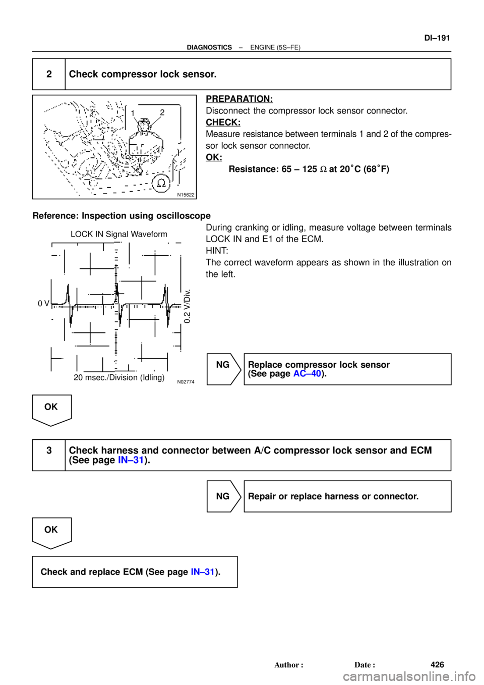
N15622
12
N02774
LOCK IN Signal Waveform
20 msec./Division (Idling) 0 V
0.2 V/Div.
± DIAGNOSTICSENGINE (5S±FE)
DI±191
426 Author�: Date�:
2 Check compressor lock sensor.
PREPARATION:
Disconnect the compressor lock sensor connector.
CHECK:
Measure resistance between terminals 1 and 2 of the compres-
sor lock sensor connector.
OK:
Resistance: 65 ± 125 W at 20°C (68°F)
Reference: Inspection using oscilloscope
During cranking or idling, measure voltage between terminals
LOCK IN and E1 of the ECM.
HINT:
The correct waveform appears as shown in the illustration on
the left.
NG Replace compressor lock sensor
(See page AC±40).
OK
3 Check harness and connector between A/C compressor lock sensor and ECM
(See page IN±31).
NG Repair or replace harness or connector.
OK
Check and replace ECM (See page IN±31).
Page 2612 of 4770
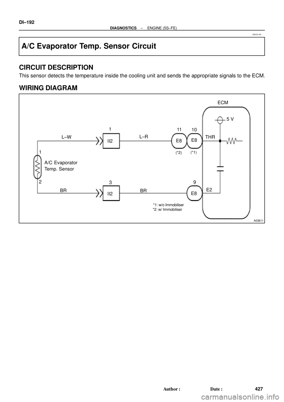
A03611
E8
II2 L±W1
L±R11
THR5 V ECM
E2
E89
BR
II23
BR A/C Evaporator
Temp. Sensor
2 1
*1: w/o Immobiliser
*2: w/ Immobiliser(*1)
(*2)
E810 DI±192
± DIAGNOSTICSENGINE (5S±FE)
427 Author�: Date�:
A/C Evaporator Temp. Sensor Circuit
CIRCUIT DESCRIPTION
This sensor detects the temperature inside the cooling unit and sends the appropriate signals to the ECM.
WIRING DIAGRAM
DI01O±04
Page 2613 of 4770

THR (+)
w/o Immobiliser
w/ Immobiliser
E1 (±)THR (+)
AC0175
Thermometer
Ice
Ohmmeter
Thermistor
More than
10 cm (3.94 in.)
± DIAGNOSTICSENGINE (5S±FE)
DI±193")
BE3840
I00180
A03031A03452
ON
E1 (±)
THR (+)
w/o Immobiliser
w/ Immobiliser
E1 (±)THR (+)
AC0175
Thermometer
Ice
Ohmmeter
Thermistor
More than
10 cm (3.94 in.)
± DIAGNOSTICSENGINE (5S±FE)
DI±193
428 Author�: Date�:
INSPECTION PROCEDURE
1 Check voltage between terminals THR and E2 of ECM connector.
PREPARATION:
(a) Remove the glove compartment (See page SF±64).
(b) Turn the ignition switch ON.
CHECK:
Measure voltage between terminals THR and E1 of the ECM
connector at each temperature.
OK:
Voltage
at 0°C (32 F): 2.2 ± 2.6 V
at 15°C (59°F): 1.4 ± 1.8 V
HINT:
As the temperature increases, the voltage decreases.
OK Check and replace ECM (See page IN±31).
NG
2 Check A/C evaporator temp. sensor.
PREPARATION:
Remove the A/C evaporator temp. sensor
(See page AC±30).
CHECK:
Check resistance between terminals 1 and 2 of the A/C evapo-
rator temp. sensor connector at each temperature.
OK:
Resistance
at 0°C (32°F): 4.6 ± 5.1 W
at 15°C (59°F): 2.1 ± 2.6 W
HINT:
As the temperature increases, the voltage decreases.
NG Replace A/C evaporator temp. sensor.
OK
Page 2614 of 4770
DI±194
± DIAGNOSTICSENGINE (5S±FE)
429 Author�: Date�:
3 Check harness and connector between A/C evaporator temp. sensor and ECM
(See page IN±31).
NG Repair or replace harness or connector.
OK
Check and replace ECM (See page IN±31).
Page 2627 of 4770

DI±207
442 Author�: Date�:
7. ENGINE OPERATING CONDITION
NOTICE:
The values given below for ºNormal Conditionº are representative values, so a vehicle may still be
no")
± DIAGNOSTICSENGINE (1MZ±FE)
DI±207
442 Author�: Date�:
7. ENGINE OPERATING CONDITION
NOTICE:
The values given below for ºNormal Conditionº are representative values, so a vehicle may still be
normal even if its value varies from those listed here. So do not decide whether a part is faulty or
not solely according to the ºNormal Conditionº here.
(a) CARB mandated signals.
TOYOTA hand±held tester displayMeasurement ItemNormal Condition*
FUEL SYS #1
Fuel System Bank 1
OPEN: Air±fuel ratio feedback stopped
CLOSED: Air±fuel ratio feedback operating
Idling after warming up: CLOSED
FUEL SYS #2
Fuel System Bank 2
OPEN: Air±fuel ratio feedback stopped
CLOSED: Air±fuel ratio feedback operating
Idling after warming up: CLOSED
CALC LOAD
Calculator Load:
Current intake air volume as a proportion of max.
intake air volumeIdling: 13.1 ~ 18.7%
Racing without load (2,500rpm): 11.7 ~ 17.3%
COOLANT TEMP.Engine Coolant Temp. Sensor ValueAfter warming up: 80 ~ 95°C (176 ~ 203°F)
SHORT FT #1Short±term Fuel Trim Bank 10 ± 20%
LONG FT #1Long±term Fuel Trim Bank 10 ± 20%
SHORT FT #2Short±term Fuel Trim Bank 20 ± 20%
LONG FT #2Long±term Fuel Trim Bank 20 ± 20%
ENGINE SPDEngine SpeedIdling: 650 ~ 750 rpm
VEHICLE SPDVehicle SpeedVehicle stopped: 0 km/h (0 mph)
IGN ADVANCEIgnition Advance:
Ignition Timing of Cylinder No. 1Idling: BTDC 10 ~ 25.0°
INTAKE AIRIntake Air Temp. Sensor ValueEquivalent to Ambient Temp.
MAFAir Flow Rate Through Mass Air Flow Meter
Idling: 3.3 ~ 4.7 gm/sec.
Racing without load (2,500 rpm):
10.4 ~ 15.4 gm/sec.
THROTTLE POS
Voltage Output of Throttle Position Sensor
Calculated as a percentage:
0 V "0%, 5 V "100%Throttle valve fully closed: 7 ~ 11 %
Throttle valve fully open: 65 ~ 75%
*: If no conditions are specifically stated for ºldlingº, it means the shift lever is at N or P position, the A/C switch
is OFF and all accessory switches are OFF.
Page 2628 of 4770

443 Author�: Date�:
TOYOTA hand±held tester displayMeasurement ItemNormal Condition*1
O2S B1, S1Voltage Output of Oxygen Sensor
Bank 1 Sensor 1Idling: 0.1 ~ 0")
DI±208
± DIAGNOSTICSENGINE (1MZ±FE)
443 Author�: Date�:
TOYOTA hand±held tester displayMeasurement ItemNormal Condition*1
O2S B1, S1Voltage Output of Oxygen Sensor
Bank 1 Sensor 1Idling: 0.1 ~ 0.9 V (0.56 ~ 0.76 V*2)
O2FT B1, S1Oxygen Sensor Fuel Trim Bank 1 Sensor 1
(Same as SHORT FT #1)0 ± 20%
O2S B1, S2Voltage Output of Oxygen Sensor
Bank 1 Sensor 2Driving 50 km/h (31 mph): 0.1 ~ 0.9 V
O2S B2, S1Voltage Output of Oxygen Sensor
Bank 2 Sensor 1Idling: 0.1 ~ 0.9 V (0.56 ~ 0.76 V*2)
O2FT B2, S1Oxygen Sensor Fuel Trim Bank 2 Sensor 1
(Same as SHORT FT #2)
0 ± 20%
A/FS B1, S1 *3Voltage Output of A/F Sensor Bank 1 Sensor 1Idling: 2.8 ~ 3.8 V
A/FS B2, S1 *3Voltage Output of A/F Sensor Bank 2 Sensor 1Idling: 2.8 ~ 3.8 V
A/FFT B1, S1 *3A/F Sensor Fuel Trim Bank 1 Sensor 1
(Same as SHORT FT #1)O ± 20%
A/FFT B2, S1 *3A/F Sensor Fuel Trim Bank 2 Sensor 1
(Same as SHORT FT #1)O ± 20%
*1: If no conditions are specifically stated for ºIdlingº, it means the shift lever is shift lever is at N or P position,
the A/C switch is OFF and all accessory switches are OFF.
*2: Only for California Specification vehicles, when you use the OBD II scan tool (excluding TOYOTA hand±
held tester).
*3: Only for California Specification vehicles, when you use the TOYOTA hand±held tester.
Page 2629 of 4770

DI±209
444 Author�: Date�:
(b) TOYOTA Enhanced Signals.
TOYOTA hand±held tester displayMeasurement ItemNormal Condition*
MISFIRE RPMEngine RPM for first misfire rangeM")
± DIAGNOSTICSENGINE (1MZ±FE)
DI±209
444 Author�: Date�:
(b) TOYOTA Enhanced Signals.
TOYOTA hand±held tester displayMeasurement ItemNormal Condition*
MISFIRE RPMEngine RPM for first misfire rangeMisfire 0: 0 rpm
MISFIRE LOADEngine load for first misfire rangeMisfire 0: 0 g/r
INJECTORFuel injection time for cylinder No.1Idling: 1.6 ~ 2.9 ms
IAC DUTY RATIOIntake Air Control Valve Duty Ratio
Opening ratio rotary solenoid type IAC valveIdling: 27 ~ 47 %
STARTER SIGStarter SignalCranking: ON
CTP SIGClosed Throttle Position SignalThrottle Fully Closed: ON
A/C SIGA/C Switch SignalA/C ON: ON
PNP SWPark/Neutral Position Switch SignalP or N position: ON
ELCTRCL LOAD SIGElectrical Load SignalDefogger switch ON: ON
STOP LIGHT SWStop Light Switch SignalStop light switch ON: ON
PS OIL PRESS SWPower Steering Oil Pressure Switch SignalTurn steering wheel: ON
FC IDLFuel Cut Idle: Fuel cut when throttle valve fully
closed, during decelerationFuel cut operating: ON
FC TAUFuel Cut TAU: Fuel cut during very light loadFuel cut operating: ON
CYL#1 ~ CYL#6Abnormal revolution variation for each cylinder0%
IGNITIONTotal number of ignition for every 1,000 revolu-
tions0 ~ 3,000
EGRT GASEGR Gas Temperature Sensor Value
EGR not operating:
Temperature between intake air temp. and
engine coolant temp.
INTAKE CTRL VSVIntake Air Control Valve VSV SignalVSV operating: ON
EGR SYSTEMEGR system operating conditionIdling: OFF
A/C CUT SIGA/C Cut SignalA/C S/W OFF: ON
FUEL PUMPFuel Pump SignalIdling: ON
EVAP (PURGE) VSVEVAP VSV SignalVSV operating: Above 30%
VAPOR PRESS VSVVapor Pressure VSV SignalVSV operating: ON (TANK)
*: If no conditions are specifically stated for ºldlingº, it means the shift lever is at N or P position, the A/C switch
is OFF and all accessory switches are OFF.
 (*2)
E919
BR
E")