B06352
S05976
Upward
Turn
Connector
B06351
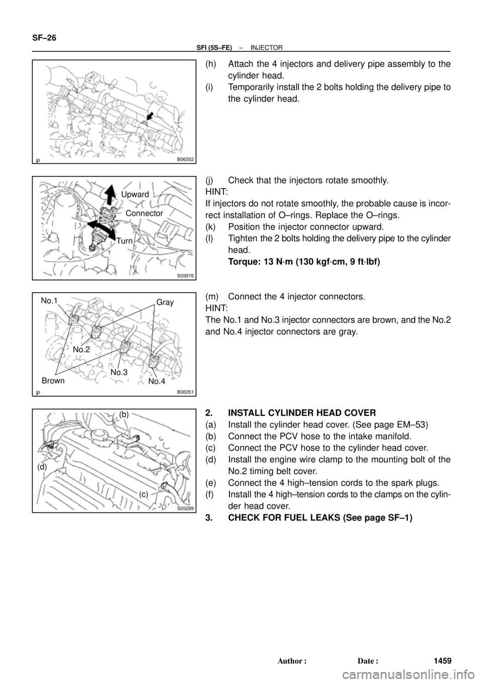
Gray
Brown No.1
No.2
No.3
No.4
S05289
(b)
(c) (d) SF±26
± SFI (5S±FE)INJECTOR
1459 Author�: Date�:
(h) Attach the 4 injectors and delivery pipe assembly to the
cylinder head.
(i) Temporarily install the 2 bolts holding the delivery pipe to
the cylinder head.
(j) Check that the injectors rotate smoothly.
HINT:
If injectors do not rotate smoothly, the probable cause is incor-
rect installation of O±rings. Replace the O±rings.
(k) Position the injector connector upward.
(l) Tighten the 2 bolts holding the delivery pipe to the cylinder
head.
Torque: 13 N´m (130 kgf´cm, 9 ft´lbf)
(m) Connect the 4 injector connectors.
HINT:
The No.1 and No.3 injector connectors are brown, and the No.2
and No.4 injector connectors are gray.
2. INSTALL CYLINDER HEAD COVER
(a) Install the cylinder head cover. (See page EM±53)
(b) Connect the PCV hose to the intake manifold.
(c) Connect the PCV hose to the cylinder head cover.
(d) Install the engine wire clamp to the mounting bolt of the
No.2 timing belt cover.
(e) Connect the 4 high±tension cords to the spark plugs.
(f) Install the 4 high±tension cords to the clamps on the cylin-
der head cover.
3. CHECK FOR FUEL LEAKS (See page SF±1)