Page 3530 of 4770

P18815
EM±24
± ENGINE MECHANICAL (1MZ±FE)TIMING BELT
1310 Author�: Date�:
10. CHECK VALVE TIMING
(a) Slowly turn the crankshaft 2 revolutions, and")
P18808
A05052
P12983
Length = 1,410 mm (55.51 in.)
P18815
EM±24
± ENGINE MECHANICAL (1MZ±FE)TIMING BELT
1310 Author�: Date�:
10. CHECK VALVE TIMING
(a) Slowly turn the crankshaft 2 revolutions, and align the tim-
ing marks of the crankshaft timing pulley and oil pump
body.
NOTICE:
Always turn the crankshaft clockwise.
(b) Check that the timing marks of the RH and LH timing pul-
leys with the timing marks of the No.3 timing belt cover as
shown in the illustration.
If the marks do not align, remove the timing belt and reinstall it.
(c) Remove the crankshaft pulley bolt.
11. INSTALL RH ENGINE MOUNTING BRACKET
Torque: 28 N´m (290 kgf´cm, 21 ft´lbf)
12. INSTALL NO.2 TIMING BELT COVER
(a) Check that the timing belt cover gasket has no cracks or
peeling, etc.
If the gasket has cracks or peeling, etc., replace it using these
steps:
�Using a screwdriver and gasket scraper, remove all
the old gasket material.
�Thoroughly clean all components to remove all the
loose material.
�Remove the backing paper from a new gasket and
install the gasket evenly to the part of the timing belt
cover shaded black in the illustration.
�After installing the gasket, press down on it so that
the adhesive firmly sticks to the timing belt cover.
(b) Install the timing belt cover with the 5 bolts.
Torque: 8.5 N´m (85 kgf´cm, 74 in.´lbf)
(c) Install the engine wire protector clamps to the No.3 timing
belt cover.
13. INSTALL TIMING BELT GUIDE
Install the timing belt guide, facing the cup side outward.
Page 3531 of 4770

Join
Line
Join
Line
Length = 460 mm
(18.11 in.)
A04693
SST
P18816
± ENGINE MECHANICAL (1MZ±FE)TIMING BELT
EM±25
1311 Author�: Date�:
14. INSTALL NO.1 TIMING BELT C")
P12982
Length = 240 mm (9.45 in.)
Join
Line
Join
Line
Length = 460 mm
(18.11 in.)
A04693
SST
P18816
± ENGINE MECHANICAL (1MZ±FE)TIMING BELT
EM±25
1311 Author�: Date�:
14. INSTALL NO.1 TIMING BELT COVER
(a) Check that the timing belt cover gaskets have cracks or
peeling, etc.
If the gasket has cracks or peeling, etc., replace it using these
steps:
�Using a screwdriver and gasket scraper, remove all
the old gasket material.
�Thoroughly clean all components to remove all the
loose material.
�Remove the backing paper from a new gasket and
install the gasket evenly to the part of the timing belt
cover shaded black in the illustration.
NOTICE:
When joining 2 gaskets, do not leave a gap between them.
Cut off any excess gasket.
�After installing the gasket, press down on it so that
the adhesive firmly sticks to the timing belt cover.
(b) Install the timing belt cover with the 4 bolts.
Torque: 8.5 N´m (85 kgf´cm, 74 in.´lbf)
15. INSTALL CRANKSHAFT PULLEY
(a) Align the pulley set key with the key groove of the pulley,
and slide on the pulley.
(b) Using SST, install the pulley bolt.
SST 09213±54015 (91651±60855), 09330±00021
Torque: 215 N´m (2,200 kgf´cm, 159 ft´lbf)
16. INSTALL NO.2 GENERATOR BRACKET
Install the generator bracket with the pivot bolt and nut. Do not
tighten the bolt yet.
Torque: (Nut): 28 N´m (290 kgf´cm, 21 ft´lbf)
17. INSTALL NO.2 RH ENGINE MOUNTING BRACKET,
ENGINE MOVING CONTROL ROD, NO.2 RH ENGINE
MOUNTING STAY (M/T) AND RH ENGINE MOUNTING
STAY (See page EM±76)
18. CONNECT GROUND STRAP CONNECTORS
19. CONNECT ENGINE COOLANT RESERVOIR HOSE TO
WATER OUTLET
20. INSTALL PS PUMP DRIVE BELT
21. INSTALL GENERATOR DRIVE BELT
(See page CH±16)
Page 3540 of 4770
CYLINDER HEAD
1320 Author�: Date�:
10. REMOVE WATER OUTLET
(a) Disconnect the ECT sender gauge connector.
(b) Disconne")
P20049Gasket
A05077
Clamp
Clamp
Clamp
S04786
EM±34
± ENGINE MECHANICAL (1MZ±FE)CYLINDER HEAD
1320 Author�: Date�:
10. REMOVE WATER OUTLET
(a) Disconnect the ECT sender gauge connector.
(b) Disconnect the ECT sensor connector.
(c) Disconnect the ground strap (connector).
(d) Disconnect the radiator hose.
(e) Disconnect the engine coolant reservoir hose.
(f) Remove the 2 bolts, 2 nuts and 2 plate washers.
(g) Disconnect the water bypass hose, and remove the water
outlet.
(h) Remove the 2 gaskets.
11. REMOVE GENERATOR DRIVE BELT
(See page CH±6)
12. REMOVE PS PUMP (See page SR±21)
13. REMOVE IGNITION COILS
14. REMOVE SPARK PLUGS
15. REMOVE TIMING BELT (See page EM±15)
16. REMOVE CAMSHAFT TIMING PULLEYS
(See page EM±15)
17. REMOVE NO.2 IDLER PULLEY (See page EM±15)
18. REMOVE NO.3 TIMING BELT COVER
(a) Disconnect the 3 engine wire clamps from the timing belt
cover.
(b) Remove the 6 bolts and timing belt cover.
19. DISCONNECT ENGINE WIRE PROTECTOR FROM
REAR SIDE
Remove the 2 nuts, and disconnect the engine wire protector
from the RH cylinder head and water inlet.
Page 3543 of 4770
CYLINDER HEAD
EM±37
1323 Author�: Date�:
29. REMOVE OIL DIPSTICK AND GUIDE
(a) Re")
P12710
O±Ring
A01816
P12811Align Intake
P12871
Main Gear
Sub±Gear
Service Bolt Intake
± ENGINE MECHANICAL (1MZ±FE)CYLINDER HEAD
EM±37
1323 Author�: Date�:
29. REMOVE OIL DIPSTICK AND GUIDE
(a) Remove the bolt holding the dipstick guide to the LH cylin-
der head.
(b) Pull out the dipstick guide together with the dipstick from
the No.1 oil pan.
(c) Remove the O±ring from the dipstick guide.
30. REMOVE CYLINDER HEAD COVERS
Remove the 8 bolts, cylinder head cover and gasket. Remove
the 2 cylinder head covers.
31. REMOVE CAMSHAFTS OF RH CYLINDER HEAD
NOTICE:
Since the thrust clearance of the camshaft is small, the
camshaft must be held level while it is being removed. If the
camshaft is not kept level, the portion of the cylinder head
receiving the shaft thrust may crack or be damaged, caus-
ing the camshaft to seize or break. To avoid this, the follow-
ing steps should be carried out.
(a) Remove the intake camshaft.
(1) Align the timing marks (2 dot marks) of the camshaft
drive and driven gears by turning the camshaft with
a wrench.
(2) Secure the exhaust camshaft sub±gear to the main
gear with a service bolt.
Recommended service bolt:
Thread diameter6 mm
Thread pitch1.0 mm
Bolt length16 ± 20 mm (0.63 ± 0.79 in.)
Page 3572 of 4770

L = 180 mm (7.09 in.)L = 72 mm (2.83 in.)
L = 335 mm (13.19 in.)L = 180 mm
(7.09 in.)
L = Length Join
LineJoin
Line
Z14262New Gasket
A01808
8
6
5
4
3
2
1
9
10
7
11
EM")
A05194
L = 133 mm (5.24 in.)
L = 180 mm (7.09 in.)L = 72 mm (2.83 in.)
L = 335 mm (13.19 in.)L = 180 mm
(7.09 in.)
L = Length Join
LineJoin
Line
Z14262New Gasket
A01808
8
6
5
4
3
2
1
9
10
7
11
EM±66
± ENGINE MECHANICAL (1MZ±FE)CYLINDER HEAD
1352 Author�: Date�: �
Remove the backing paper from a new gasket and
install the gasket evenly to the part of the timing belt
cover shaded black in the illustration.
NOTICE:
When joining 2 gaskets, do not leave a gap between them.
Cut off any excess gasket.
�After installing the gasket, press down on it so that
the adhesive firmly sticks to the timing belt cover.
(b) Install the timing belt cover with the 6 bolts.
Torque: 8.5 N´m (85 kgf´cm, 74 in.´lbf)
(c) Install the 3 engine wire clamps to the timing belt cover.
20. INSTALL NO.2 IDLER PULLEY (See page EM±21)
21. INSTALL CAMSHAFT TIMING PULLEYS
(See page EM±21)
22. INSTALL TIMING BELT (See page EM±21)
23. INSTALL SPARK PLUGS
24. INSTALL IGNITION COILS
25. INSTALL PS PUMP DRIVE BELT
26. INSTALL GENERATOR DRIVE BELT
(See page SR±28)
27. INSTALL WATER OUTLET
(a) Install 2 new gaskets.
(b) Connect the water outlet to the bypass hose.
(c) Install the water outlet with the 2 bolts, 2 nuts and 2 plate
washers. Alternately tighten the bolts and nuts.
Torque: 15 N´m (150 kgf´cm, 11 ft´lbf)
NOTICE:
Do not scratch the seal surface of the water outlet with the
stud bolt.
(d) Connect the ECT sender gauge connector.
(e) Connect the ECT sensor connector.
(f) Connect the ground strap (connector).
(g) Connect the radiator hose.
(h) Connect the engine coolant reservoir hose.
28. INSTALL INTAKE MANIFOLD ASSEMBLY
(a) Install the intake manifold, delivery pipe and injectors as-
sembly with the 9 bolts, 2 plate washers and 2 nuts. Uni-
formly tighten the bolts and nuts, in several passes, in the
sequence shown.
Torque: 15 N´m (150 kgf´cm, 11 ft´lbf)
Page 3741 of 4770
LU028±03
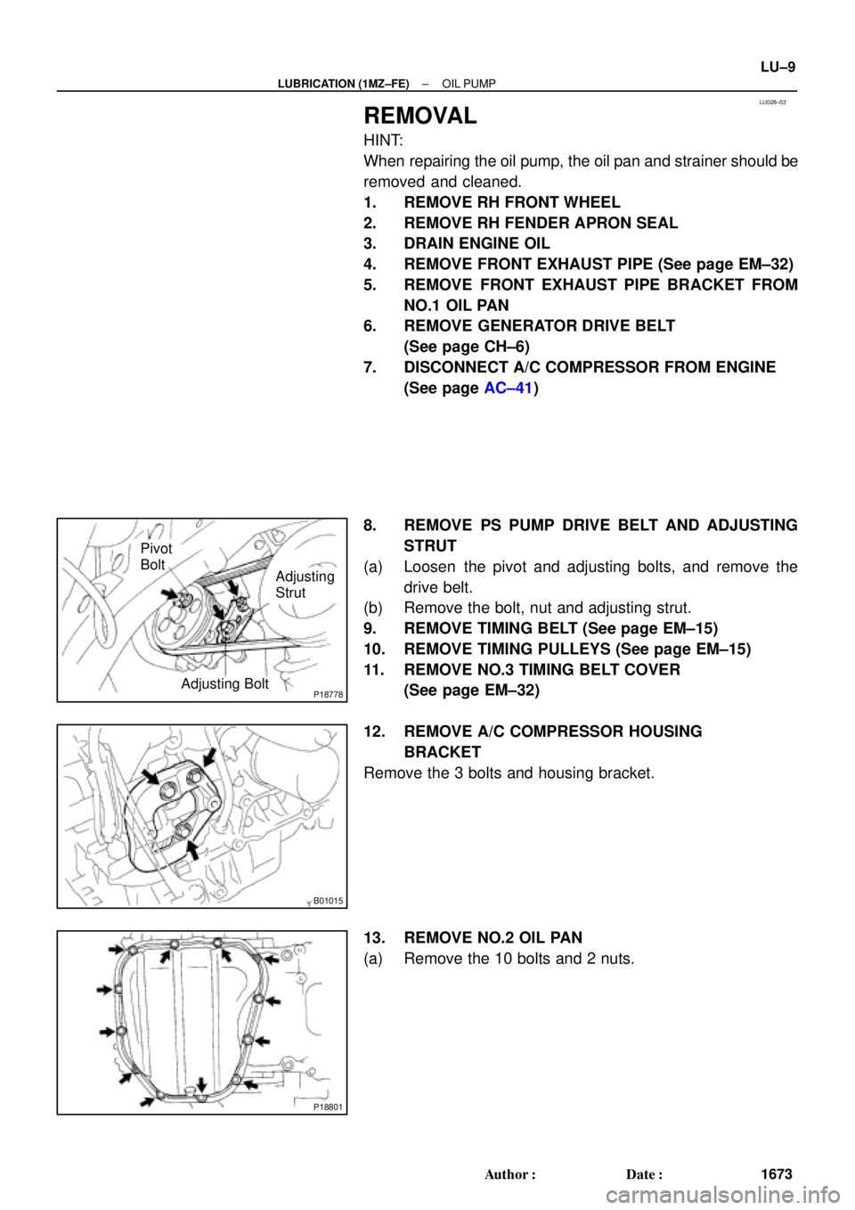
P18778Adjusting Bolt
Adjusting
Strut Pivot
Bolt
B01015
P18801
± LUBRICATION (1MZ±FE)OIL PUMP
LU±9
1673 Author�: Date�:
REMOVAL
HINT:
When repairing the oil pump, the oil pan and strainer should be
removed and cleaned.
1. REMOVE RH FRONT WHEEL
2. REMOVE RH FENDER APRON SEAL
3. DRAIN ENGINE OIL
4. REMOVE FRONT EXHAUST PIPE (See page EM±32)
5. REMOVE FRONT EXHAUST PIPE BRACKET FROM
NO.1 OIL PAN
6. REMOVE GENERATOR DRIVE BELT
(See page CH±6)
7. DISCONNECT A/C COMPRESSOR FROM ENGINE
(See page AC±41)
8. REMOVE PS PUMP DRIVE BELT AND ADJUSTING
STRUT
(a) Loosen the pivot and adjusting bolts, and remove the
drive belt.
(b) Remove the bolt, nut and adjusting strut.
9. REMOVE TIMING BELT (See page EM±15)
10. REMOVE TIMING PULLEYS (See page EM±15)
11. REMOVE NO.3 TIMING BELT COVER
(See page EM±32)
12. REMOVE A/C COMPRESSOR HOUSING
BRACKET
Remove the 3 bolts and housing bracket.
13. REMOVE NO.2 OIL PAN
(a) Remove the 10 bolts and 2 nuts.
Page 3750 of 4770
OIL PUMP
1682 Author�: Date�:
(b) Apply seal packing to the No.2 oil pan as shown in the il-
lustration.
Seal packing:
Part No. 08826�")
P12568
A
A
BB
Seal Width
4 ± 5 mm LU±18
± LUBRICATION (1MZ±FE)OIL PUMP
1682 Author�: Date�:
(b) Apply seal packing to the No.2 oil pan as shown in the il-
lustration.
Seal packing:
Part No. 08826±00080 or equivalent
�Install a nozzle that has been cut to a 4 ± 5 mm (0.16
± 0.20 in.) opening.
HINT:
Avoid applying an excessive amount to the surface.
�Parts must be assembled within 3 minutes of ap-
plication. Otherwise the material must be removed
and reapplied.
�Immediately remove nozzle from the tube and rein-
stall cap.
(c) Install the No.2 oil pan with the 10 bolts and 2 nuts. Uni-
formly tighten the bolts and nuts in several passes.
Torque: 8 N´m (80 kgf´cm, 69 in.´lbf)
7. INSTALL A/C COMPRESSOR HOUSING BRACKET
Torque: 25 N´m (250 kgf´cm, 18 ft´lbf)
8. INSTALL NO.3 TIMING BELT COVER
(See page EM±21)
9. INSTALL TIMING PULLEYS (See page EM±21)
10. INSTALL TIMING BELT (See page EM±21)
11. INSTALL ADJUSTING STRUT AND PS PUMP DRIVE
BELT
(a) Temporarily install the adjusting strut with the bolt and the
nut.
(b) Install the drive belt with the pivot and adjusting bolts.
Torque: 43.1 N´m (440 kgf´cm, 32 ft´lbf)
(c) Tighten the nut.
Torque: 43.1 N´m (440 kgf´cm, 32 ft´lbf)
12. INSTALL A/C COMPRESSOR (See page AC±47)
13. INSTALL GENERATOR DRIVE BELT
(See page CH±16)
14. INSTALL FRONT EXHAUST PIPE BRACKET TO
NO.1 OIL PAN
Torque: 21 N´m (210 kgf´cm, 15 ft´lbf)
15. INSTALL FRONT EXHAUST PIPE (See page EM±76)
16. REMOVE RH FENDER APRON SEAL
17. REMOVE RH FRONT WHEEL
18. FILL ENGINE WITH OIL
19. START ENGINE AND CHECK FOR LEAKS
20. RECHECK ENGINE OIL LEVEL
Page 4056 of 4770

(e)
(d)
B06353
B06354
SF±22
± SFI (5S±FE)INJECTOR
1455 Author�: Date�:
REMOVAL
1. REMOVE CYLINDER HEAD COVER
(a) Disconnect the 4 high±tension cords from the clamps on
the cy")
SF0DI±03
S05289
(c)
(e)
(d)
B06353
B06354
SF±22
± SFI (5S±FE)INJECTOR
1455 Author�: Date�:
REMOVAL
1. REMOVE CYLINDER HEAD COVER
(a) Disconnect the 4 high±tension cords from the clamps on
the cylinder head cover.
(b) Disconnect the 4 high±tension cords from the spark
plugs.
(c) Disconnect the PCV hose from the intake manifold.
(d) Disconnect the PCV hose from the cylinder head cover.
(e) Disconnect the engine wire clamp from the mounting bolt
of the No.2 timing belt cover.
(f) Remove the cylinder head cover. (See page EM±33)
NOTICE:
Cover the cylinder head with a clean cloth to prevent dirt,
etc. getting into the cylinder head.
2. REMOVE DELIVERY PIPE AND INJECTORS
(a) Disconnect the 4 injector connectors.
(b) Remove the 2 bolts holding the delivery pipe to the cylin-
der head.
(c) Disconnect the delivery pipe from the 4 injectors.
(d) Pull out the 4 injectors.
NOTICE:
Be careful not to drop the injectors.
(e) Remove the 4 insulators (Except California) and 2
spacers from the cylinder head.
(f) California:
Remove the 2 O±rings, insulator and grommet from each
injector.
(g) Except California:
Remove the O±ring and grommet from each injector.