Page 2068 of 4770

2456 Author�: Date�:
DISASSEMBLY
1. REMOVE THESE PARTS:
(a) Release handle
(b) Front seat cushion shield
(c) Vertical Seat Adjust")
BO0MQ±01
H01870
BO±108
± BODYFRONT SEAT (Manual Seat for TMMK Made)
2456 Author�: Date�:
DISASSEMBLY
1. REMOVE THESE PARTS:
(a) Release handle
(b) Front seat cushion shield
(c) Vertical Seat Adjuster:
Vertical adjuster knob
(d) Front seat cushion lower shield
(e) Front seatback hinge cover.
(f) w/ Lumber Support:
Lumber support lever
(g) Headrest
(h) Front seat inner belt
2. REMOVE SEATBACK ASSEMBLY
(a) w/ Side Airbag Assembly:
Remove the side airbag wire harness after removing
clips.
(b) Remove the hog rings.
(c) Remove the bolts and seatback assembly.
3. REMOVE SEATBACK COVER
(a) w/ Side Airbag Assembly:
Remove the hook from the seatback frame.
(b) Remove the headrest supports.
(c) Remove the seatback frame from the seatback cover with
pad.
(d) Remove the seatback cover from the seatback pad.
4. w/ Side Airbag Assembly:
REMOVE SIDE AIRBAG ASSEMBLY
Remove the 2 nuts and side airbag assembly from the seatback
frame.
CAUTION:
�Do not store the side airbag assembly with the airbag
deployment direction facing down.
�Never disassemble the side airbag assembly.
5. REMOVE SEAT CUSHION ASSEMBLY
Remove the 4 bolts and seat cushion assembly from the seat
adjuster.
6. REMOVE SEAT CUSHION COVER
(a) Remove the seat cushion frame.
(b) Remove the seat cushion cover from the seat cushion
pad.
7. REMOVE RECLINING CONNECTING PIPE
Remove the reclining connecting pipe.
8. REMOVE SEAT TRACK ADJUSTING HANDLE
Remove the seat track adjusting handle.
9. REMOVE OUTER ADJUSTER SUB±ASSEMBLY
Remove the outer adjuster sub±assembly from the inner ad-
juster sub±assembly.
Page 2071 of 4770
H01870
H01871
± BODYFRONT SEAT (Manual Seat for TMMK Made)
BO±111
2459 Author�: Date�:
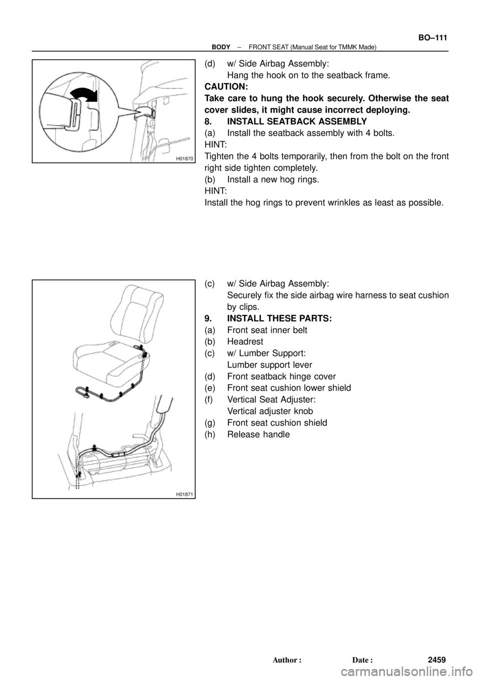
(d) w/ Side Airbag Assembly:
Hang the hook on to the seatback frame.
CAUTION:
Take care to hung the hook securely. Otherwise the seat
cover slides, it might cause incorrect deploying.
8. INSTALL SEATBACK ASSEMBLY
(a) Install the seatback assembly with 4 bolts.
HINT:
Tighten the 4 bolts temporarily, then from the bolt on the front
right side tighten completely.
(b) Install a new hog rings.
HINT:
Install the hog rings to prevent wrinkles as least as possible.
(c) w/ Side Airbag Assembly:
Securely fix the side airbag wire harness to seat cushion
by clips.
9. INSTALL THESE PARTS:
(a) Front seat inner belt
(b) Headrest
(c) w/ Lumber Support:
Lumber support lever
(d) Front seatback hinge cover
(e) Front seat cushion lower shield
(f) Vertical Seat Adjuster:
Vertical adjuster knob
(g) Front seat cushion shield
(h) Release handle
Page 2073 of 4770
BO0NA±01
H01874
Headrest SupportHeadrest
Seatback Frame
Seatback Pad
Seatback Cover
RH Seatback
Hinge
Center Seatback Hinge
Rear Seat center
Armrest
Center Armrest
Hinge Cover
LH Seatback Hinge
Seat Cushion Cover
Seat Cushion Pad Seatback Locking Knob
Seatback Lock Knob Gromet
Rear Seatback Lock Control
Rear Seatback lock
Control Bezel Seatback Lock control Cable
: Specified torque
N´m (kgf´cm, ft´lbf)
RH Rear Side
Seatback
LH Rear Side
Seatback
18 (185, 13)
18 (185, 13)
18 (185, 13)
17.5 (178, 12.5)
18 (185, 13)
Seat Belt Guide
± BODYREAR SEAT (TMC Made)
BO±113
2461 Author�: Date�:
REAR SEAT (TMC Made)
COMPONENTS
Page 2074 of 4770
BO0NB±01
BO±114
± BODYREAR SEAT (TMC Made)
2462 Author�: Date�:
REMOVAL
1. REMOVE LH SEATBACK ASSEMBLY
(a) Release lock to lean the seat back to front.
(b) Remove the clips.
(c) Remove the 2 bolts and LH seatback assembly.
2. REMOVE RH SEAT BACK ASSEMBLY
(a) Release lock to lean the seatback to front.
(b) Remove the clips.
(c) Remove the 2 bolts and RH seatback assembly.
3. REMOVE SEAT CUSHION ASSEMBLY
(a) Remove the seat cushion assembly.
HINT:
Remove the rear seat inner with center belt from seat cushion slit to remove the seat cushion.
(b) Remove the 2 lock hooks.
4. REMOVE LH AND RH REAR SIDE SEATBACK
(a) Remove the bolt and LH rear side seatback.
(b) Remove the bolt and RH rear side seatback.
5. REMOVE SEATBACK HINGE
(a) Remove the bolts and LH seatback hinge and RH seatback hinge.
(b) Remove the 2 bolts and center seatback hinge.
Torque: 18 N´m (185 kgf´cm, 13 ft´lbf)
Page 2078 of 4770
BO0N5±01
H01875
Rear seatback Board
Rear Seatback frame
RH Rear Side
SeatbackRear Seatback CoverRear Seatback PadHeadrest
Support
LH Seatback Hinge Seatback Lock Knob
Seatback Lock Knob
Cover
Rear Seatback Lock
Control Cable
Rear Seatback
Control Bezel
Seat Cushion Cover LH Side Seatback Headrest
Headrest Suppot
Seatback Pad
Seatback Cover
Seat Cushion Pad
Child Restraint Seat Headrest
Rear Seatback Lock
Control
Center Seatback
Hinge
Center Seatback
Hinge
: Specified torque
N´m (kgf´cm, ft´lbf)
RH Seatback Hinge
Rear Seat center
Armrest
18 (185, 13)18 (185, 13)
18 (185, 13)Center Armrest
Hinge Cover18 (185, 13)
18 (185, 13)
7.8 (79, 69 in.´lbf)
42 (428, 31)
13 (130, 9)
17.5 (178, 12.5)
Child Restraint
Seat Coverw/ CRS: BO±118
± BODYREAR SEAT (TMMK Made)
2466 Author�: Date�:
REAR SEAT (TMMK Made)
COMPONENTS
Page 2079 of 4770

BO±119
2467 Author�: Date�:
REMOVAL
1. REMOVE SEAT CUSHION ASSEMBLY
(a) Remove the seat cushion assembly.
HINT:
Remove the rear seat inner with center belt from")
BO0N6±01
± BODYREAR SEAT (TMMK Made)
BO±119
2467 Author�: Date�:
REMOVAL
1. REMOVE SEAT CUSHION ASSEMBLY
(a) Remove the seat cushion assembly.
HINT:
Remove the rear seat inner with center belt from seat cushion slit to remove the seat cushion.
(b) Remove the 2 lock hooks.
2. REMOVE LH SEATBACK ASSEMBLY
(a) Release lock to lean the seatback to front.
(b) Remove the 2 bolts and LH seatback assembly.
3. w/ CRS:
REMOVE CHILD RESTRAINT SEAT
(a) Remove child restraint seat cover.
(b) Remove the 3 bolts and 2 nuts.
Torque: 13 N´m (130 kgf´cm, 9 ft´lbf)
(c) Remove the child restraint seat.
4. w/o CRS:
REMOVE RH SEATBACK ASSEMBLY
(a) Release lock to lean the seatback to front.
(b) Remove the clips.
(c) Remove the bolts and RH seatback assembly.
5. w/ CRS:
REMOVE RH SEATBACK ASSEMBLY
(a) Remove the 3 bolts.
Torque:
RH bolt: 7.8 N´m (80 kgf´cm, 69 in.´lbf)
Center bolt: 42 N´m (428 kgf´cm, 31 ft´lbf)
(b) Remove the RH seatback assembly.
6. REMOVE LH AND RH REAR SIDE SEATBACK
(a) Remove the bolt and LH rear side seatback.
(b) Remove the bolt and RH rear side seatback.
7. REMOVE SEATBACK HINGE
(a) Remove the bolt and LH seatback hinge.
(b) Remove the 2 bolts and center seatback hinge.
Torque: 18 N´m (185 kgf´cm, 13 ft´lbf)
(c) w/o CRS:
Remove the bolt and RH seatback hinge.
Torque: 18 N´m (185 kgf´cm, 13 ft´lbf)
Page 3622 of 4770
BO0L2±01
H01975
Door Lock
Cylinder
Outside Handle Front Door Belt Moulding
Door Glass
Door FrameFront Door Upper Moulding
Outside
Rear View
Mirror
Door Glass
Run
5.5 (55, 49 in.´lbf)
5.5 (55, 49 in.´lbf)
5.0 (50, 43 in.´lbf)�
Door Lock
23 (230, 17)
Window Regulator
8.0 (80, 69 in.´lbf)
Door Hinge
X6
7.5 (75, 66 in.´lbf)
Regulator
Motor
X3
31 (310, 22)
26 (260, 19)
8.0 (80, 71 in.´lbf)
30 (300, 22)
31 (310, 22)
Door
Check
Door Hinge
26 (260, 19)
Speaker
Power Window Switch Rear Lower
FrameFront Lower
FrameFront Window Upper
Garnish
Inside Handle Bezel
3.5 (35, 31 in.´lbf)
Driver's Side:
Regulator
Motor
Ptdt
N´m (kgf´cm, ft´lbf) : Specified torqueInside Handle
Door Trim
� Precoated part Door Lock StrikerService Hole Cover BO±12
± BODYFRONT DOOR
2370 Author�: Date�:
2001 CAMRY (RM819U)
FRONT DOOR
COMPONENTS
Page 3626 of 4770
BO0L4±01
N20966SST
N20967
BO2556
BO±16
± BODYFRONT DOOR
2374 Author�: Date�:
2001 CAMRY (RM819U)
ADJUSTMENT
1. ADJUST DOOR IN FORWARD/REARWARD AND VER-
TICAL DIRECTIONS
Using SST, adjust the door by loosening the body side hinge
bolts.
SST 09812±00020
Torque: 31 N´m (310 kgf´cm, 22 ft´lbf)
2. ADJUST DOOR IN LEFT/RIGHT AND VERTICAL
DIRECTIONS
To adjust, loosen the door side hinge.
HINT:
Substitute the bolt and washer for the centering bolt.
Torque: 26 N´m (260 kgf´cm, 19 ft´lbf)
3. ADJUST DOOR LOCK STRIKER
(a) Check that door fits and the door lock linkages are ad-
justed correctly.
(b) Loosen the striker mounting screws to adjust.
(c) Using a plastic hammer, tap the striker to adjust it.
Torque: 23 N´m (230 kgf´cm, 17 ft´lbf)


5.5 (55, 49 in")