Page 1974 of 4770
BO0L4±01
N20966SST
N20967
BO2556
± BODYFRONT DOOR
BO±15
2363 Author�: Date�:
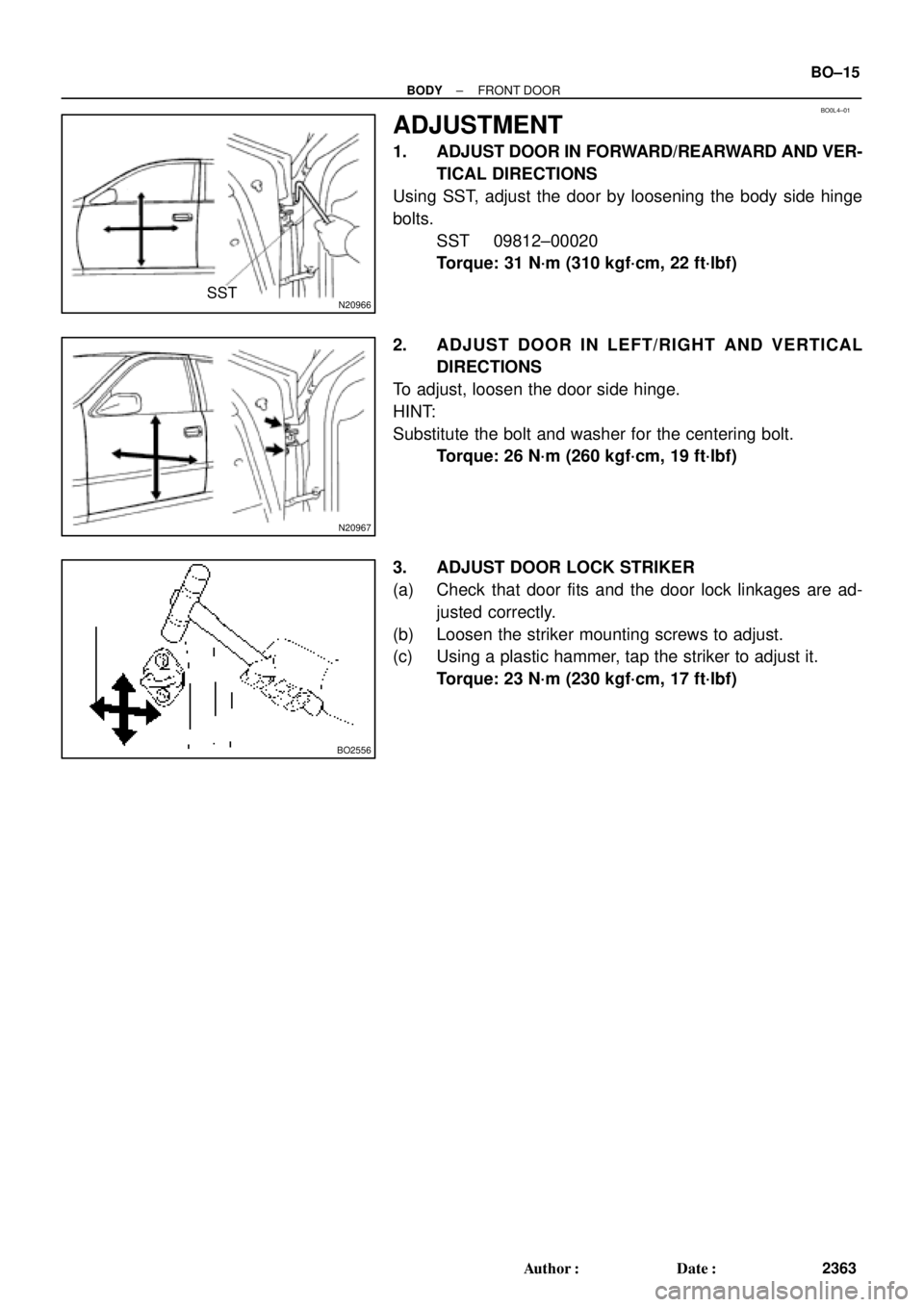
ADJUSTMENT
1. ADJUST DOOR IN FORWARD/REARWARD AND VER-
TICAL DIRECTIONS
Using SST, adjust the door by loosening the body side hinge
bolts.
SST 09812±00020
Torque: 31 N´m (310 kgf´cm, 22 ft´lbf)
2. ADJUST DOOR IN LEFT/RIGHT AND VERTICAL
DIRECTIONS
To adjust, loosen the door side hinge.
HINT:
Substitute the bolt and washer for the centering bolt.
Torque: 26 N´m (260 kgf´cm, 19 ft´lbf)
3. ADJUST DOOR LOCK STRIKER
(a) Check that door fits and the door lock linkages are ad-
justed correctly.
(b) Loosen the striker mounting screws to adjust.
(c) Using a plastic hammer, tap the striker to adjust it.
Torque: 23 N´m (230 kgf´cm, 17 ft´lbf)
Page 1976 of 4770
BO0L6±01
H01733
Door LockRear Door Upper
Moulding
Door Belt Moulding
Door Glass
Outside handle
Door Glass Run
Door Lock
Door Lock Striker
Rear Side Frame
Rear Door WeatherstripWindow Regulator
Inside Handle BezelInside HandleWindow
Regulator
Motor Child Protector
Lock Lever Cover
Snap Ring
Regulator
Handle Plate Door Trim Service Hole Cover Power Window
Switch Cover Door HingeDoor Hinge
Door Check w/o Power Door
Lock:
w/o Power Window:
: Specified torque
N´m (kgf´cm, ft´lbf)
3.5 (35, 31 in.´lbf)
5.5 (55, 49 in.´lbf)
5.5 (55, 49 in.´lbf)
23 (230, 17)
7.0 (70, 61 in.´lbf)
Door Lock Control Link
Door Lock Remote
Control Link
5.0 (50, 43 in.´lbf)
8.0 (80, 71 in.´lbf)
26 (260, 19)
8.0 (80, 71 in.´lbf)
30 (300, 22)
26 (260, 19)
± BODYREAR DOOR
BO±17
2365 Author�: Date�:
REAR DOOR
COMPONENTS
Page 1980 of 4770
 Remove the front part of t")
BO0L7±01
N21006
3 Clips
2 Clips
N20972
N20973
BO2556
± BODYREAR DOOR
BO±21
2369 Author�: Date�:
ADJUSTMENT
1. ADJUST DOOR IN FORWARD/REARWARD AND VER-
TICAL DIRECTION
(a) Remove the front part of the rear seat side garnish.
(b) Remove the rear part of the front door inside scuff plate.
(c) Remove the center pillar lower garnish.
HINT:
Pull both sides of the top and bottom part of the garnish out-
ward, then pull out to remove the garnish.
(d) Loosen the body side hinge nuts to adjust.
Torque: 26 N´m (260 kgf´cm, 19 ft´lbf)
(e) Install center pillar lower garnish.
(f) Install front door inside scuff plate.
(g) Install rear seat side garnish.
2. ADJUST DOOR IN LEFT/RIGHT AND VERTICAL
DIRECTIONS
Loosen the door side hinge bolts to adjust.
HINT:
Substitute a bolt with washer for the centering bolt.
Torque: 26 N´m (260 kgf´cm, 19 ft´lbf)
3. ADJUST DOOR LOCK STRIKER
(a) Check that the door fit and door lock linkages are adjusted
correctly.
(b) Loosen the striker mounting screws to adjust.
Torque: 23 N´m (230 kgf´cm, 17 ft´lbf)
(c) Using a plastic hammer, tap the striker to adjust it.
Page 1986 of 4770
BO0LD±01
H01747
Torsion Bar
Luggage Compart-
ment Door Hinge
Luggage Compart-
ment Door Hinge
Luggage Compartment
Door
Luggage Compartment
Door Trim
Left Side Luggage
Trim
Finish Side Trim
Rear Luggage Trim
Rear Seat CushionRoom Partition TrimPackage Tray Trim
High Mounted
Stop Light
Rear SeatbackFinish Side Trim Door Lock
Door Lock StrikerLeft Hand Back
Up LightRight Hand
Back Up Light Right Side Luggage
Trim
: Specified torque
N´m (kgf´cm, ft´lbf)
Lock Cylinder
Luggage Compart-
ment Floor Mat
8.0 (80, 71 in.´lbf)
8.0 (80, 71 in.´lbf)
5.5 (55, 49 in.´lbf)
5.5 (55, 49 in.´lbf)
± BODYLUGGAGE COMPARTMENT DOOR AND HINGE
BO±27
2375 Author�: Date�:
LUGGAGE COMPARTMENT DOOR AND HINGE
COMPONENTS
Page 1987 of 4770

BO0LE±01
N22588
121
N21430
: 4 Clips
N22591
BO±28
± BODYLUGGAGE COMPARTMENT DOOR AND HINGE
2376 Author�: Date�:
REMOVAL
1. REMOVE LUGGAGE COMPARTMENT DOOR TRIM
2. REMOVE LUGGAGE COMPARTMENT DOOR
(a) Disconnect the connector.
(b) Using a clip remover, disconnect the clamps.
(c) Remove the 4 bolts and door.
Torque: 8.0 N´m (80 kgf´cm, 71 in.´lbf)
3. REMOVE THESE PARTS:
(a) Luggage compartment floor mat
(b) LH and RH rear floor finish side plates
(c) Inner cover trims
(d) Rear seat
(e) Room partition trims
4. REMOVE HIGH±MOUNTED STOP LIGHT
(a) Push on the both side of the cover to release the claws by
your hand and remove the cover as shown in the illustra-
tion.
(b) Remove the 2 bolts and stop light, then disconnect the
connector.
5. REMOVE ROOF SIDE INNER GARNISH
(a) Remove the clip.
(b) Using a screwdriver, pry loose and remove the garnish.
HINT:
Tape the screwdriver tip before use.
6. REMOVE PACKAGE TRAY TRIM
7. REMOVE TORSION BAR
(a) Remove the torsion bar from the center bracket.
Page 1988 of 4770
BO4010
SST
BO4011
SST
BO4012
SST
± BODYLUGGAGE COMPARTMENT DOOR AND HINGE
BO±29
2377 Author�: Date�:
(b) Install SST to the torsion bar on the hinge side.
SST 09804±24010
(c) Push down on SST, and pull the luggage compartment
door hinge from the torsion bar.
(d) Slowly lift SST, and remove the torsion bar from the tor-
sion bar bracket with SST.
(e) Remove the torsion bar.
(f) Repeat for the other side.
Page 1989 of 4770
BO0LF±01
BO±30
± BODYLUGGAGE COMPARTMENT DOOR AND HINGE
2378 Author�: Date�:
DISASSEMBLY
1. REMOVE DOOR LOCK
(a) Disconnect the control link.
(b) Remove the 2 bolts and lock.
Torque: 5.5 N´m (56 kgf´cm, 49 in.´lbf)
2. REMOVE REAR COMBINATION LIGHT
(a) Disconnect the connector.
(b) Remove the 10 nuts and rear combination lights.
Page 1990 of 4770
BO0LG±01
N22589
N22590
± BODYLUGGAGE COMPARTMENT DOOR AND HINGE
BO±31
2379 Author�: Date�:
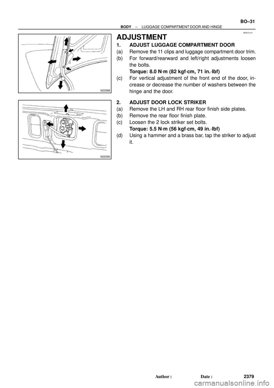
ADJUSTMENT
1. ADJUST LUGGAGE COMPARTMENT DOOR
(a) Remove the 11 clips and luggage compartment door trim.
(b) For forward/rearward and left/right adjustments loosen
the bolts.
Torque: 8.0 N´m (82 kgf´cm, 71 in.´lbf)
(c) For vertical adjustment of the front end of the door, in-
crease or decrease the number of washers between the
hinge and the door.
2. ADJUST DOOR LOCK STRIKER
(a) Remove the LH and RH rear floor finish side plates.
(b) Remove the rear floor finish plate.
(c) Loosen the 2 lock striker set bolts.
Torque: 5.5 N´m (56 kgf´cm, 49 in.´lbf)
(d) Using a hammer and a brass bar, tap the striker to adjust
it.