Page 728 of 4770
 Description
The side airbag sensor assembly is mounted on the right and left center pillars. It receives signals fr")
CAMRY ± NEW FEATURES19
4. Construction and Operation
Side Airbag Sensor Assembly
1) Description
The side airbag sensor assembly is mounted on the right and left center pillars. It receives signals from
the side airbag sensor enclosed in the side airbag sensor assembly and judges whether the side airbag must
be activated or not.
2) Construction and Operation
The side airbag sensor assembly consists of side airbag sensor, safing sensor, etc.
a. Side Airbag Sensor
The side airbag sensor is enclosed in the side airbag sensor assembly based on the acceleration of the
vehicle that occurs during a side collision. The distortion created in the sensor is converted into an elec-
tric signal. This signal is a linear representation of the acceleration rate.
b. Safing Sensor
The safing sensor is enclosed in the side airbag sensor assembly. The sensor turns ON if an acceleration
force that is higher than a predetermined value is applied to the safing sensor as a result of a side colli-
sion.
Airbag Sensor Assembly
1) Description
The airbag sensor assembly is mounted on the center floor under the instrument panel.
When the airbag sensor assembly receives the airbag activation signal from the side airbag sensor assem-
bly, it applies current to the inflator.
Furthermore, the airbag sensor assembly diagnoses a system malfunction of the side airbag system.
This is the same airbag sensor assembly that is used for the
SRS airbag for the driver and front passenger.
2) Construction and Operation
The airbag sensor assembly consists of ignition control circuit, back up power source, diagnosis circuit,
memory circuit, etc.
a. Ignition Control Circuit
The ignition control circuit performs a prescribed calculation based on the signal output by the airbag
sensor and the front airbag sensor. If these calculated values are larger than a predetermined value, it
activates the ignition operation.
b. Back-Up Power Source
The back-up power source consists of a back-up capacitor and a DC-DC converter. In case of a power
system failure during a collision, the back-up capacitor discharges and supplies electric power to the
system. The DC-DC converter is a boosting transformer when the battery voltage drops below a certain
level.
c. Diagnosis Circuit
This circuit constantly diagnoses the system for any malfunction. When a malfunction is detected, it
lights up the
SRS warning light on the combination meter to alert the driver.
d. Memory Circuit
When a malfunction is detected by the diagnosis circuit, it is coded and stored in this memory circuit.
Page 907 of 4770
'99camry U
141
Fan speed selector
Turn the knob to adjust the fan speedÐto
the right to increase, to the left to de-
crease.
Temperature selector
Turn the knob to adjust the temperatureÐ
to the right to warm, to the left to cool.
Air flow selector
Turn the knob to select the vents used for
air flow.
1. PanelÐAir flows mainly from the
instrument panel vents.
2. Bi±levelÐAir flows from both the floor
vents and the instrument panel vents.
3. FloorÐAir flows mainly from the floor
vents.
4. Floor/WindshieldÐAir flows mainly
from the floor vents and windshield
vents.
5. WindshieldÐAir flows mainly from the
windshield vents.For details about air flow selector settings,
see the illustration after ºA/Cº button.
Turning the Air Flow Selector to wind-
shield position turns on the defroster to
clear the front view more quickly.
Page 910 of 4770

Air intakeÐFRESH (outside air)
Air flowÐFLOOR
Air cond")
'99camry U
144
Heating
For best results, set controls to:
Fan speedÐAny setting except ºOFFº
TemperatureÐTo w a r d s WARM
(red zone)
Air intakeÐFRESH (outside air)
Air flowÐFLOOR
Air conditioningÐOFF
�For quick heating, select recirculated
air for a few minutes. To keep the
windows from fogging, select fresh af-
ter the vehicle interior has been
warmed.
�Press the ºA/Cº button on for dehumidi-
fied heating.
�Choose floor/windshield air flow to heat
the vehicle interior while defrosting or
defogging the windshield.Air conditioning
For best results, set controls to:
Fan speedÐAny setting except ºOFFº
TemperatureÐTo w a r d s COLD
(blue zone)
Air intakeÐFRESH (outside air)
Air flowÐPANEL
Air conditioningÐON
�For quick cooling, move the air intake
selector to recirculate for a few min-
utes.
Ventilation
For best results, set controls to:
Fan speedÐAny setting except ºOFFº
TemperatureÐTo w a r d s COLD
(blue zone)
Air intakeÐFRESH (outside air)
Air flowÐPANEL
Air conditioningÐOFF
Defogging
The inside of the windshield
For best results, set controls to:
Fan speedÐAny setting except ºOFFº
TemperatureÐTo w a r d s WARM
(red zone) to heat;
COLD (blue zone) to
cool
Air intakeÐFRESH (outside air)
Air flowÐWINDSHIELD
Turning the Air Flow Selector to wind-
shield position turns on the defroster to
clear the front view more quickly.
Press the ºA/Cº button for dehumidified
heating or cooling. This setting clears the
front view more quickly.
�On humid days, do not blow cold air
on the windshieldÐthe difference be-
tween the outside and inside tempera-
tures could make the fogging worse.
Page 911 of 4770
'99camry U
145
Defrosting
The outside of the windshield
For best results, set controls to:
Fan speedÐAny setting except ºOFFº
TemperatureÐTo w a r d s WARM
(red zone)
Air intakeÐFRESH (outside air)
Air flowÐWINDSHIELD
Turning the Air Flow Selector to wind-
shield position turns on the defroster to
clear the front view more quickly.
Press the ºA/Cº button for dehumidified
heating. This setting clears the front view
more quickly.
�To heat the vehicle interior while de-
frosting the windshield, choose
floor/windshield air flow.
ÐSide vents
If air flow control is not satisfactory, check
the side vents. The side vents may be
opened or closed as shown.
Page 913 of 4770
'99camry U
147
Part 1
OPERATION OF
INSTRUMENTS AND
CONTROLSÐ
Chapter 1±8
Other equipment
�Clock
�Cigarette lighter and ashtrays
�Power outlet
�G lov e box
�Garage door opener box
�Miscellaneous box
�Auxiliary box
�Cup holder
�Traction control system
�Floor mat
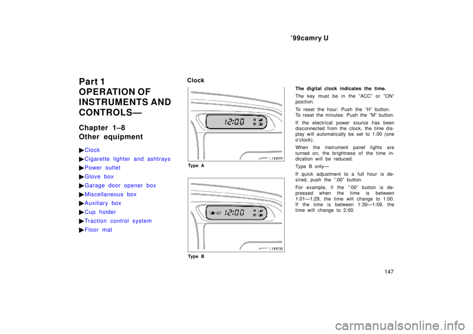
Clock
Ty p e A
Ty p e B
The digital clock indicates the time.
The key must be in the ºACCº or ºONº
position.
To reset the hour: Push the ºHº button.
To reset the minutes: Push the ºMº button.
If the electrical power source has been
disconnected from the clock, the time dis-
play will automatically be set to 1:00 (one
o'clock).
When the instrument panel lights are
turned on, the brightness of the time in-
dication will be reduced.
Type B onlyÐ
If quick adjustment to a full hour is de-
sired, push the º:00º button.
For example, if the º:00º button is de-
pressed when the time is between
1:01Ð1:29, the time will change to 1:00.
If the time is between 1:30Ð1:59, the
time will change to 2:00.
Page 922 of 4770
'99camry U
156
Floor mat
Use a floor mat of the correct size.
If the floor carpet and floor mat have a
hole, then it is designed for use with a
locking clip. Fix the floor mat with locking
clip into the hole in the floor carpet.
CAUTION
Make sure the floor mat is properly
placed on the floor carpet. If the floor
mat slips and interferes with the
movement of the pedals during driv-
ing, it may cause an accident.
Page 961 of 4770

'99camry U
165
Even if the anti±lock brake system should
fail, the brake system will still operate
conventionally. However, when the ºABSº
warning light is on (and the brake system
warning light is off), the anti±lock brake
system is not assisting brake performance
so that the wheels can lock±up during
sudden braking or braking on slippery
road surfaces. Have your vehicle checked
by your Toyota dealer as soon as pos-
sible.
DRUM±IN±DISC TYPE PARKING BRAKE
SYSTEM (1MZ±FE engine)
Your vehicle has a drum±in±disc type
parking brake system. This type of brake
system needs bedding±down of the brake
shoes periodically or whenever the parking
brake shoes and/or drums are replaced.
Have your Toyota dealer perform the bed-
ding±down.
Brake pad wear limit indicators
The brake pad wear limit indicators on
your disc brakes give a warning noise
when the brake pads are worn to where
replacement is required.
If you hear a squealing or scraping noise
while driving, have the brake pads
checked and replaced by your Toyota
dealer as soon as possible. Expensive ro-
tor damage can result if the pads are not
replaced when necessary.
Luggage stowage precautions
When stowing luggage or cargo in the
vehicle, observe the following:
�Put luggage or cargo in the trunk when
at all possible. Be sure all items are
secured in place.
�Be careful to keep the vehicle bal-
anced. Locating the weight as far for-
ward as possible helps maintain bal-
ance.
�For better fuel economy, do not carry
unneeded weight.
CAUTION
�To prevent luggage or packages
from sliding forward during braking,
do not stack anything in the en-
larged trunk. Keep luggage or pack-
ages low, as close to the floor as
possible.
Page 965 of 4770

'99camry U
169
Part 3
STARTING AND
DRIVING
�Before starting the engine
�How to start the engine
�Tips for driving in various
conditions
�Winter driving tips
�Tr ailer towing
�How to save fuel and make
your vehicle last longer, too
Before starting the engine
1. Check the area around the vehicle be-
fore entering it.
2. Adjust seat position, seatback angle,
head restraint height and steering
wheel angle.
3. Adjust inside and outside rear view
mirrors.
4. Lock all doors.
5. Fasten seat belts.1. Apply the parking brake firmly.
2. Turn off unnecessary lights and acces-
sories.
3.Manual transmission: Press the clutch
pedal to the floor and shift the trans-
mission into neutral. Hold the clutch
pedal to the floor until the engine is
started. A starter safety device will pre-
vent the starter from operating if the
clutch pedal is not fully depressed.
Automatic transmission: Put the se-
lector lever in ºPº. If you need to re-
start the engine while the vehicle is
moving, put the selector lever in ºNº.
A starter safety device will prevent the
starter from operating if the selector
lever is in any drive position.
4.Automatic transmission only: De-
press the brake pedal and hold it to
the floor until driving off.
How to start the engineÐ
(a) Before cranking


Air intakeÐFRESH (outside")