2000 TOYOTA CAMRY tail lights
[x] Cancel search: tail lightsPage 1001 of 4770

'99camry U
205
Tire surface and wheel nuts
Check the tires carefully for cuts, damage
or excessive wear. See Chapter 7±2 for
additional information. When checking the
tires, make sure no nuts are missing, and
check the nuts for looseness. Tighten
them if necessary.
Tire rotation
Rotate the tires every 12000 km (7500
miles). See Chapter 7±2 for additional in-
formation.
Fluid leaks
Check underneath for leaking fuel, oil, wa-
ter or other fluid after the vehicle has
been parked for a while. If you smell fuel
fumes or notice any leak, have the cause
found and corrected immediately.
Doors and engine hood
Check that all doors including trunk lid
operate smoothly and all latches lock se-
curely. Make sure the engine hood sec-
ondary latch secures the hood from open-
ing when the primary latch is released.
INSIDE THE VEHICLE
Items listed below should be checked
regularly, e.g. while performing periodic
services, cleaning the vehicle, etc.Lights
Make sure the headlights, stop lights, tail
lights, turn signal lights, and other lights
are all working. Check headlight aim.
Service reminder indicators and warning
buzzers
Check that all service reminder indicators
and warning buzzers function properly.
Steering wheel
Be alert for changes in steering condition,
such as hard steering or strange noise.
Seats
Check that all front seat controls such as
seat adjusters, seatback recliner, etc. op-
erate smoothly and that all latches lock
securely in any position. Check that the
head restraints move up and down
smoothly and that the locks hold securely
in any latched position. For folding±down
rear seatbacks, check that the latches
lock securely.
Seat belts
Check that the seat belt system such as
buckles, retractors and anchors operate
properly and smoothly. Make sure that the
belt webbings not cut, frayed, worn or
damaged.Accelerator pedal
Check the pedal for smooth operation and
uneven pedal effort or catching.
Clutch pedal
Check the pedal for smooth operation.
Brake pedal
Check the pedal for smooth operation and
that the pedal has the proper clearance.
Check the brake booster function.
Brakes
At a safe place, check that the brakes do
not pull to one side when applied.
Parking brake
Check that the lever has the proper travel
and that, on a safe incline, your vehicle
is held securely with only the parking
brake applied.
Automatic transmission ºParkº mecha-
nism
Check the lock release button of the se-
lector lever for proper and smooth opera-
tion. On a safe incline, check that your
vehicle is held securely with the selector
lever in ºPº position and all brakes re-
leased.
Page 1012 of 4770

'99camry U
246
27. STOP 15 A: Stop lights, cruise control
system, high±mounted stoplight, anti±
lock brake system, shift lock control
system, multiport fuel injection system/
sequential multiport fuel injection sys-
tem
28. TAIL 10 A: Parking lights, license plate
lights, tail lights, front side marker
lights, daytime running light system,
multiport fuel injection system/sequen-
tial multiport fuel injection system
29. POWER±OUTLET 15 A: Power outlet
30. OBD 7.5 A: On±board diagnosis sys-
tem
31. FOG 15 A: No circuit
32. STARTER 5 A: Gauges and meters,
Multiport fuel injection system/sequen-
tial multiport fuel injection system
33. DOOR 25 A: Power door lock system,
theft deterrent system, fuel filler door
control system34. PANEL 7.5 A: Gauge and meter, audio
system, cigarette lighter, glove box
light, clock, instrument panel light con-
trol, service reminder indicators, air
conditioning control panel lights, ash-
tray light, emergency flasher, seat heat-
er control system, daytime running light
system, rear window defogger, electron-
ically controlled automatic transmission
system
35. TURN 7.5 A: Emergency flasher
36. RAD±NO.2 7.5 A: Audio system, power
antenna
37. CIG 15 A: Cigarette lighter, shift lock
control system, power rear view mirror
controls, theft deterrent system, power
door lock system, SRS airbag system,
seat belt pretensioners, outside rear
view mirror defogger, air conditioning
system
Fuses (type B)
38. CDS 30 A: Electric cooling fans
39. RDI 30 A: Electric cooling fans
40. MAIN 40 A: ºHEAD RH(UPR)º, ºHEAD
RHº, ºH±LP RH(LWR)º fuses
41. HTR 50 A: ºAM1º, ºA/Cº fuses
42. DEF 40 A: Rear window defogger43. PWR 30 A: Power window control sys-
tem, power seat, electric moon roof
44. AM1 40 A: Head lamp cleaner
45. T±STK 40 A or CDS NO.2 30 A: No
Circuit
Fuses (type C)
46. ALT 100 A: ºRDIº, ºCDSº fuses
47. ABS 60 A: Anti±lock brake system
Page 1099 of 4770
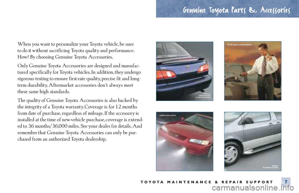
When you want to personalize your Toyota vehicle, be sure
to do it without sacrificing Toyota quality and performance.
How? By choosing Genuine Toyota Accessories.
Only Genuine Toyota Accessories are designed and manufac-
tured specifically for Toyota vehicles. In addition, they undergo
rigorous testing to ensure first- rate quality, precise fit and long-
term durability. Aftermarket accessories don’ t always meet
these same high standards.
The quality of Genuine Toyota Accessories is also backed by
the integrity of a Toyota warranty. Coverage is for 12 months
from date of purchase, regardless of mileage. If the accessory is
installed at the time of new- vehicle purchase, coverage is extend-
ed to 36 months/36,000 miles. See your dealer for details. And
remember that Genuine Toyota Accessories can only be pur-
chased from an authorized Toyota dealership.
Genuine Toyota Parts & Accessories
TOYOTA MAINTENANCE & REPAIR SUPPORT7
SIENNA
RUNNING BOARDS CAMRY FOG LIGHTS VIP SECURITY SYSTEM RS3000
COROLLA
REAR SPOILER
& GOLD PACKAGE
Page 1251 of 4770

HEADLIGHT (w/ DAYTIME RUNNING LIGHT)
The current from the FL MAIN is always flowing from the MAIN fuse to HEAD relay (Coil side) to TERMINAL H±LP of the
daytime running light relay (Main), from DOME fuse to TERMINAL +B of the daytime running light relay (Main) and from the
ALT fuse to Taillight relay (Coil side) to TERMINAL TAIL (TMMK Made) of the daytime running light relay (Main).
When the ignition SW is turned on, the current flowing through the GAUGE fuse flows to TERMINAL IG of the daytime
running light relay (Main).
1. DAYTIME RUNNING LIGHT OPERATION
When the engine is started, voltage generated at TERMINAL L of the generator is applied to TERMINAL CHG± of the
daytime running light relay (Main). If the parking brake lever is pulled up (Parking brake SW on) at this time, the relay is not
activated so the daytime running light system does not operate. If the parking brake lever is then released (Parking brake
SW off), a signal is input to TERMINAL PKB of the relay.
This activates the daytime running light relay (Main) and the HEAD relay is turned to on, so the current flows from the MAIN
fuse to the HEAD relay (Point side) to TERMINAL 1 of the DIM relay to TERMINAL 4 to H±LP LH (LWR), H±LP RH (LWR)
fuses to TERMINAL 1 of the headlights to TERMINAL 3 to TERMINAL 1 of the daytime running light resistor to TERMINAL 2
to GROUND, causing the headlights to light up (Headlights light up dimmer than normal brightness.). Once the daytime
running light system operates and the headlights light up, the headlights remain on even if the parking brake lever is pulled
up (Parking brake SW on).
If the engine stalls and the ignition SW remains on, the headlights remain light up even through current is no longer output
from TERMINAL L of the generator. If the ignition SW is then turned off, the headlights go off.
If the engine is started with the parking brake lever released (Parking brake SW off), the daytime running light system
operates and headlights light up when the engine starts.
2. HEADLIGHT OPERATION
When the light control SW is switched to HEAD position and the dimmer SW is set to LOW position, causing the daytime
running light relay (Main) and the HEAD relay to turn on, so the current flows from the MAIN fuse to HEAD relay (Point side)
to DRL NO.2 fuse to TERMINAL 3 of the DRL NO.4 relay to TERMINAL 4 to TERMINAL H±ON of the daytime running light
relay (Main) to TERMINAL H to TERMINAL 3 of the integration relay to TERMINAL 4 to TERMINAL 13 of the light control
SW to TERMINAL 16 to GROUND, activating the DRL. NO.4 relay. The current to HEAD relay (Point side) then flows to
TERMINAL 1 of the DIM relay to TERMINAL 4 to H±LP LH (LWR), H±LP RH (LWR) fuses to TERMINAL 1 of the headlights
to TERMINAL 3 to TERMINAL 1 of the DRL NO.4 relay to TERMINAL 2 to GROUND, causing the headlights to light up at
normal intensity.
When the light control SW is switched to HEAD position and the dimmer SW is set to HIGH position, the signal from the
dimmer SW is input to the daytime running light relay (Main). This activates the daytime running light relay (Main) and the
HEAD relay is turned on, so the current flows from the MAIN fuse to HEAD relay (Point side) to TERMINAL 1 of the DIM
relay to TERMINAL 3 to TERMINAL DIM of the daytime running light relay (Main), activating the DIM relay. This causes
current to flow from TERMINAL 1 of the DIM relay to TERMINAL 2 to HEAD LH (UPR), HEAD RH (UPR) fuses to TERMINAL
2 of the headlights to TERMINAL 3 to TERMINAL 1 of the DRL NO.4 relay to TERMINAL 2 to GROUND, causing the
headlights to light up at high beam and the high beam indicator light to light up.
When the dimmer SW is switched to FLASH position, the signal from the dimmer SW is input to the daytime running light
relay (Main). This activates the daytime running light relay (Main) and the HEAD relay is turned on, so the current flows from
the MAIN fuse to HEAD relay (Point side) to DRL NO.2 fuse to TERMINAL 3 of the DRL NO.4 relay to TERMINAL 4 to
TERMINAL H±ON of the daytime running light relay (Main) to TERMINAL H to TERMINAL 8 of the dimmer SW to
TERMINAL 16 to GROUND, activating the DRL NO.4 relay. At the same time, the current flows from the TERMINAL 1 of the
DIM relay to TERMINAL 3 to TERMINAL DIM of the daytime running light relay (Main), activating the DIM relay, and also
flows from the HEAD LH (UPR), HEAD RH (UPR) fuses to TERMINAL 2 of the headlights to TERMINAL 3 to TERMINAL 1 of
the DRL NO.4 relay to TERMINAL 2 to GROUND, causing the headlights to light up at high beam and the high beam
indicator light to light up.
SYSTEM OUTLINE
Page 1252 of 4770
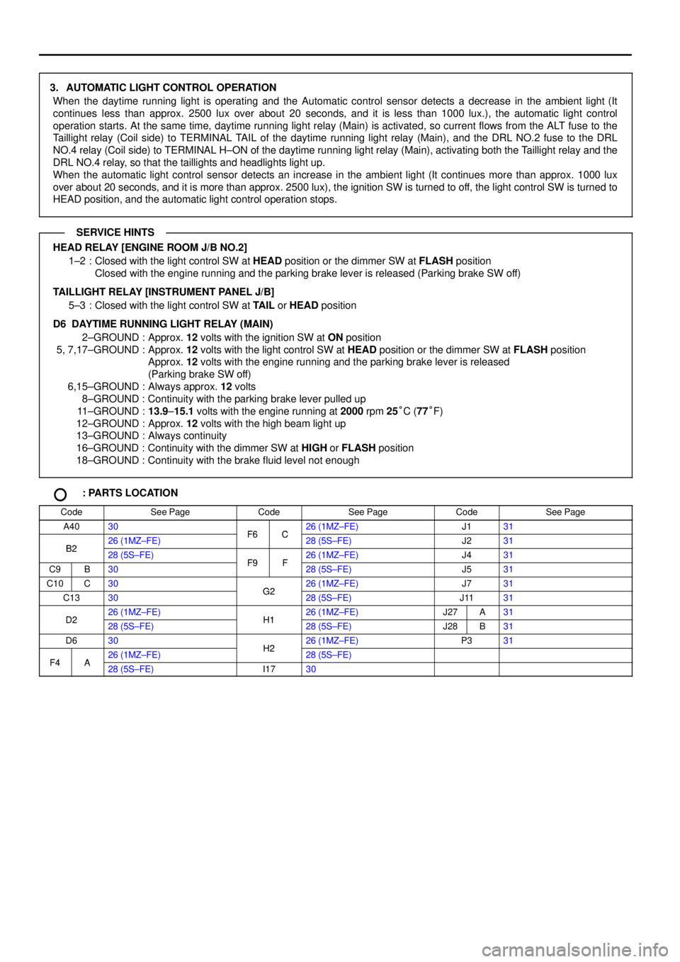
3. AUTOMATIC LIGHT CONTROL OPERATION
When the daytime running light is operating and the Automatic control sensor detects a decrease in the ambient light (It
continues less than approx. 2500 lux over about 20 seconds, and it is less than 1000 lux.), the automatic light control
operation starts. At the same time, daytime running light relay (Main) is activated, so current flows from the ALT fuse to the
Taillight relay (Coil side) to TERMINAL TAIL of the daytime running light relay (Main), and the DRL NO.2 fuse to the DRL
NO.4 relay (Coil side) to TERMINAL H±ON of the daytime running light relay (Main), activating both the Taillight relay and the
DRL NO.4 relay, so that the taillights and headlights light up.
When the automatic light control sensor detects an increase in the ambient light (It continues more than approx. 1000 lux
over about 20 seconds, and it is more than approx. 2500 lux), the ignition SW is turned to off, the light control SW is turned to
HEAD position, and the automatic light control operation stops.
HEAD RELAY [ENGINE ROOM J/B NO.2]
1±2 : Closed with the light control SW at HEAD position or the dimmer SW at FLASH position
Closed with the engine running and the parking brake lever is released (Parking brake SW off)
TAILLIGHT RELAY [INSTRUMENT PANEL J/B]
5±3 : Closed with the light control SW at TAIL or HEAD position
D6 DAYTIME RUNNING LIGHT RELAY (MAIN)
2±GROUND : Approx. 12 volts with the ignition SW at ON position
5, 7,17±GROUND : Approx. 12 volts with the light control SW at HEAD position or the dimmer SW at FLASH position
Approx. 12 volts with the engine running and the parking brake lever is released
(Parking brake SW off)
6,15±GROUND : Always approx. 12 volts
8±GROUND : Continuity with the parking brake lever pulled up
11±GROUND :13.9±15.1 volts with the engine running at 2000 rpm 25°C (77°F)
12±GROUND : Approx. 12 volts with the high beam light up
13±GROUND : Always continuity
16±GROUND : Continuity with the dimmer SW at HIGH or FLASH position
18±GROUND : Continuity with the brake fluid level not enough
: PARTS LOCATION
CodeSee PageCodeSee PageCodeSee Page
A4030F6C26 (1MZ±FE)J131
B226 (1MZ±FE)F6C28 (5S±FE)J231B228 (5S±FE)F9F26 (1MZ±FE)J431
C9B30F9F28 (5S±FE)J531
C10C30G226 (1MZ±FE)J731
C1330G228 (5S±FE)J1131
D226 (1MZ±FE)H126 (1MZ±FE)J27A31D228 (5S±FE)H128 (5S±FE)J28B31
D630H226 (1MZ±FE)P331
F4A26 (1MZ±FE)H228 (5S±FE)F4A28 (5S±FE)I1730
SERVICE HINTS
Page 1258 of 4770
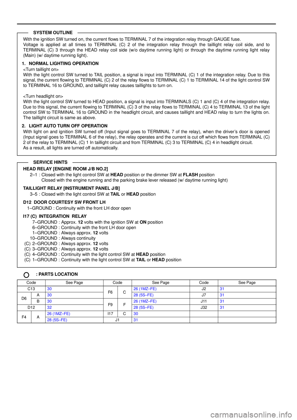
With the ignition SW turned on, the current flows to TERMINAL 7 of the integration relay through GAUGE fuse.
Voltage is applied at all times to TERMINAL (C) 2 of the integration relay through the taillight relay coil side, and to
TERMINAL (C) 3 through the HEAD relay coil side (w/o daytime running light) or through the daytime running light relay
(Main) (w/ daytime running light).
1. NORMAL LIGHTING OPERATION
With the light control SW turned to TAIL position, a signal is input into TERMINAL (C) 1 of the integration relay. Due to this
signal, the current flowing to TERMINAL (C) 2 of the relay flows to TERMINAL (C) 1 to TERMINAL 14 of the light control SW
to TERMINAL 16 to GROUND, and taillight relay causes taillights to turn on.
With the light control SW turned to HEAD position, a signal is input into TERMINALS (C) 1 and (C) 4 of the integration relay.
Due to this signal, the current flowing to TERMINAL (C) 3 of the relay flows to TERMINAL (C) 4 to TERMINAL 13 of the light
control SW to TERMINAL 16 to GROUND in the headlight circuit, and causes taillight and HEAD relay to turn the lights on.
The taillight circuit is same as above.
2. LIGHT AUTO TURN OFF OPERATION
With light on and ignition SW turned off (Input signal goes to TERMINAL 7 of the relay), when the driver's door is opened
(Input signal goes to TERMINAL 6 of the relay), the relay operates and the current is cut off which flows from TERMINAL (C)
2 of the relay to TERMINAL (C) 1 In taillight circuit and from TERMINAL (C) 3 to TERMINAL (C) 4 in headlight circuit.
As a result, all lights are turned off automatically.
HEAD RELAY [ENGINE ROOM J/B NO.2]
2±1 : Closed with the light control SW at HEAD position or the dimmer SW at FLASH position
Closed with the engine running and the parking brake lever released (w/ daytime running light)
TAILLIGHT RELAY [INSTRUMENT PANEL J/B]
3±5 : Closed with the light control SW at TAIL or HEAD position
D12 DOOR COURTESY SW FRONT LH
1±GROUND : Continuity with the front LH door open
I17 (C)
INTEGRATION RELAY
7±GROUND : Approx. 12 volts with the ignition SW at ON position
6±GROUND : Continuity with the front LH door open
1±GROUND : Always approx. 12 volts
10±GROUND : Always continuity
(C) 2±GROUND : Always approx. 12 volts
(C) 3±GROUND : Always approx. 12 volts
(C) 4±GROUND : Continuity with the light control SW at HEAD position
(C) 1±GROUND : Continuity with the light control SW at TAIL or HEAD position
: PARTS LOCATION
CodeSee PageCodeSee PageCodeSee Page
C1330F6C26 (1MZ±FE)J231
D6A30F6C28 (5S±FE)J731D6B30F9F26 (1MZ±FE)J1131
D1232F9F28 (5S±FE)J3231
F4A26 (1MZ±FE)I17C30F4A28 (5S±FE)J131
SYSTEM OUTLINE
SERVICE HINTS
Page 1280 of 4770
5 3
5 3
BL B11 9 3
W± B W± BW±B G±O
G±OG
LIGHT FAILURE SENSOR REAR COMBINATION
LIGHT RH REAR COMBINATION
LIGHT LH
R11 R 9
L 3
W± BG
114 8 10A
GAU GE FROM POWER S OURCE SYS TEM (
SEE PAGE 50)
1S 11D2
IF2 5C 7
A 3D D
R±L
R±L Y±G Y±G
R±L
REAR LIGHTS
WARNING LIGHT
[COMB. METER] JUNCTION
CONNECTOR J 4
3 4
3 4
B 9B 7 B10
A
A W± BG±O G±O
W±B W±B
G±O
G±O TAI L LI GHT RH
[REAR COMB. LIGHT RH] TAI L LI GHT L H
[REAR COMB. LIGHT LH]
R10 R 8
J UNCTION
CONNECTOR J40
W±B
DELAY
B11
BP
W±B
W±BC C 8 A , C10 * 1 : TMMK MADE W/ DAYTIME RUNNING LIGHT
* 2 : EXCEPT * 1
* 3 : TMC MADE
TAIL SIDE
MARKER
TAIL SIDE
MARKER
B 8
11 G
(
*3)
G
(
*3)
G
(
*3)G
(
*3)
Page 1281 of 4770
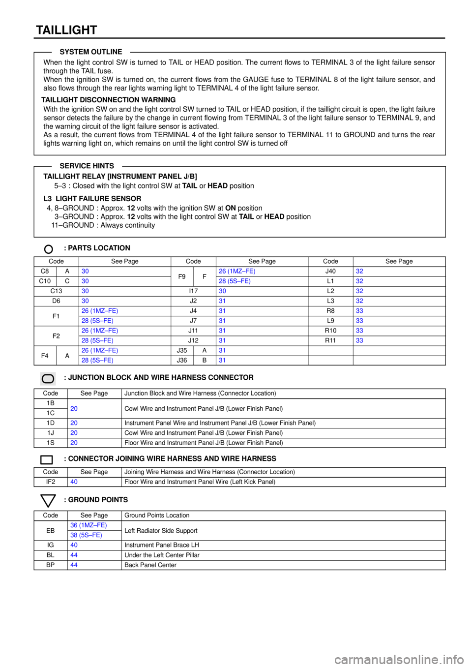
TAILLIGHT
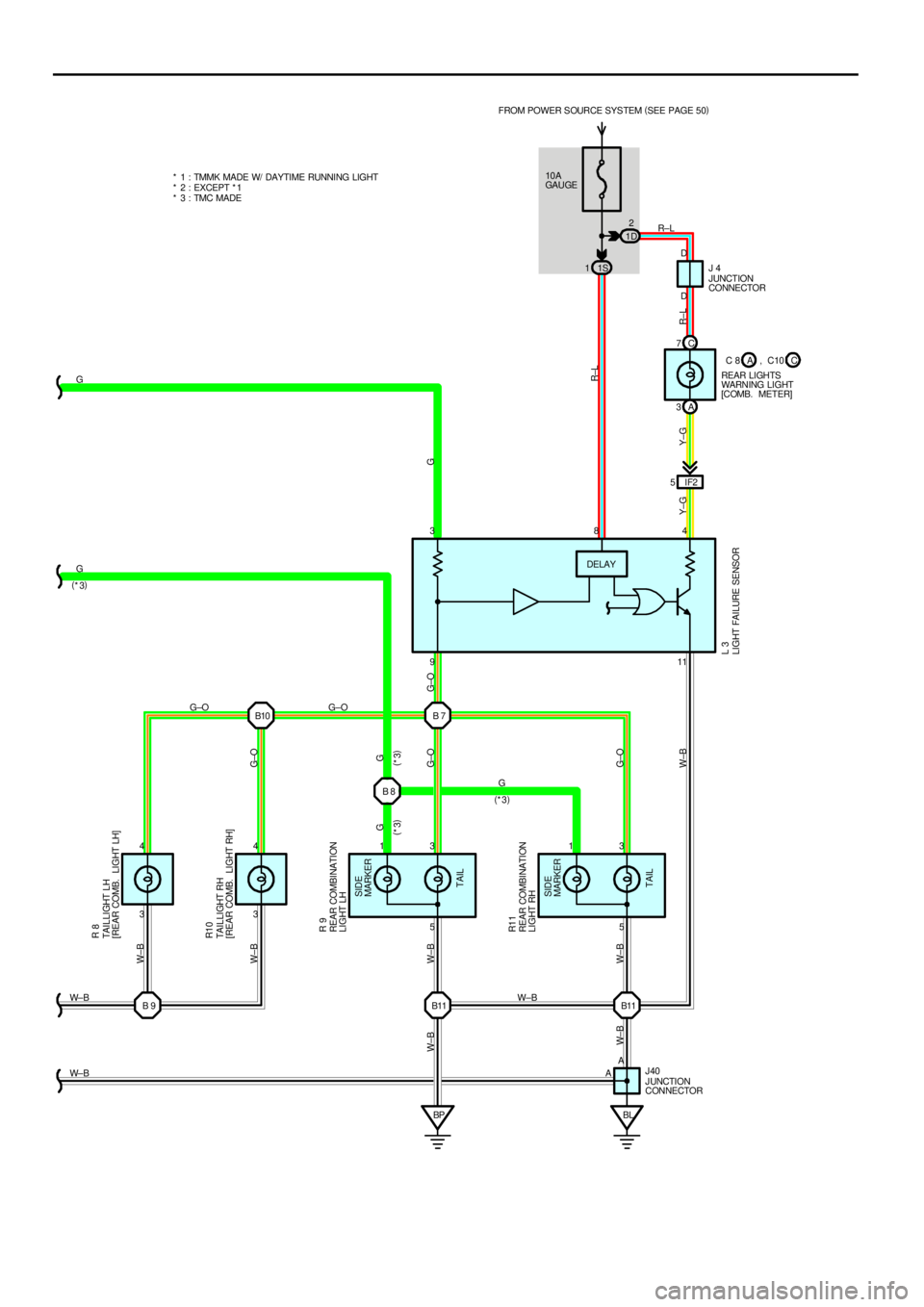
When the light control SW is turned to TAIL or HEAD position. The current flows to TERMINAL 3 of the light failure sensor
through the TAIL fuse.
When the ignition SW is turned on, the current flows from the GAUGE fuse to TERMINAL 8 of the light failure sensor, and
also flows through the rear lights warning light to TERMINAL 4 of the light failure sensor.
TAILLIGHT DISCONNECTION WARNING
With the ignition SW on and the light control SW turned to TAIL or HEAD position, if the taillight circuit is open, the light failure
sensor detects the failure by the change in current flowing from TERMINAL 3 of the light failure sensor to TERMINAL 9, and
the warning circuit of the light failure sensor is activated.
As a result, the current flows from TERMINAL 4 of the light failure sensor to TERMINAL 11 to GROUND and turns the rear
lights warning light on, which remains on until the light control SW is turned off
TAILLIGHT RELAY [INSTRUMENT PANEL J/B]
5±3 : Closed with the light control SW at TAIL or HEAD position
L3 LIGHT FAILURE SENSOR
4, 8±GROUND : Approx. 12 volts with the ignition SW at ON position
3±GROUND : Approx. 12 volts with the light control SW at TAIL or HEAD position
11±GROUND : Always continuity
: PARTS LOCATION
CodeSee PageCodeSee PageCodeSee Page
C8A30F9F26 (1MZ±FE)J4032
C10C30F9F28 (5S±FE)L132
C1330I1730L232
D630J231L332
F126 (1MZ±FE)J431R833F128 (5S±FE)J731L933
F226 (1MZ±FE)J1131R1033F228 (5S±FE)J1231R1133
F4A26 (1MZ±FE)J35A31F4A28 (5S±FE)J36B31
: JUNCTION BLOCK AND WIRE HARNESS CONNECTOR
CodeSee PageJunction Block and Wire Harness (Connector Location)
1B20Cowl Wire and Instrument Panel J/B (Lower Finish Panel)1C20Cowl Wire and Instrument Panel J/B (Lower Finish Panel)
1D20Instrument Panel Wire and Instrument Panel J/B (Lower Finish Panel)
1J20Cowl Wire and Instrument Panel J/B (Lower Finish Panel)
1S20Floor Wire and Instrument Panel J/B (Lower Finish Panel)
: CONNECTOR JOINING WIRE HARNESS AND WIRE HARNESS
CodeSee PageJoining Wire Harness and Wire Harness (Connector Location)
IF240Floor Wire and Instrument Panel Wire (Left Kick Panel)
: GROUND POINTS
CodeSee PageGround Points Location
EB36 (1MZ±FE)Left Radiator Side SupportEB38 (5S±FE)Left Radiator Side Support
IG40Instrument Panel Brace LH
BL44Under the Left Center Pillar
BP44Back Panel Center
SYSTEM OUTLINE
SERVICE HINTS