Page 4297 of 4770

Z15498
Oil
PS Gear
Closed
SSTPS Vane
Pump Reservoir
Z15499
Oil
PS Gear
SSTPS Vane
Pump Reservoir
Open
Z15500
Oil
PS Gear
SSTPS Vane
Pump Reservoir
Lock Position
± STEERINGPOWER STEERING FLUID
SR±7
2102 Author�: Date�:
(f) With the engine idling, close the valve of the SST and ob-
serve the reading on the SST.
Minimum fluid pressure:
7,845 kPa (80 kgf´cm
2, 1,138 psi)
NOTICE:
�Do not keep the valve closed for more than 10 se-
conds.
�Do not let the fluid temperature become too high.
(g) With the engine idling, open the valve fully.
(h) Measure the fluid pressure at engine speeds of 1,000 rpm
and 3,000 rpm.
Difference fluid pressure:
490 kPa (5 kgf´cm
2, 71 psi) or less
NOTICE:
Do not turn the steering wheel.
(i) With the engine idling and valve fully opened, turn the
steering wheel to full lock.
Minimum fluid pressure:
7,845 kPa (80 kgf´cm
2, 1,138 psi)
NOTICE:
�Do not maintain lock position for more than 10 se-
conds.
�Do not let the fluid temperature become too high.
(j) Disconnect the SST.
(k) Connect the pressure feed tube.
(See page SR±28)
(l) Bleed the power steering system.
(See page SR±4)
Page 4310 of 4770
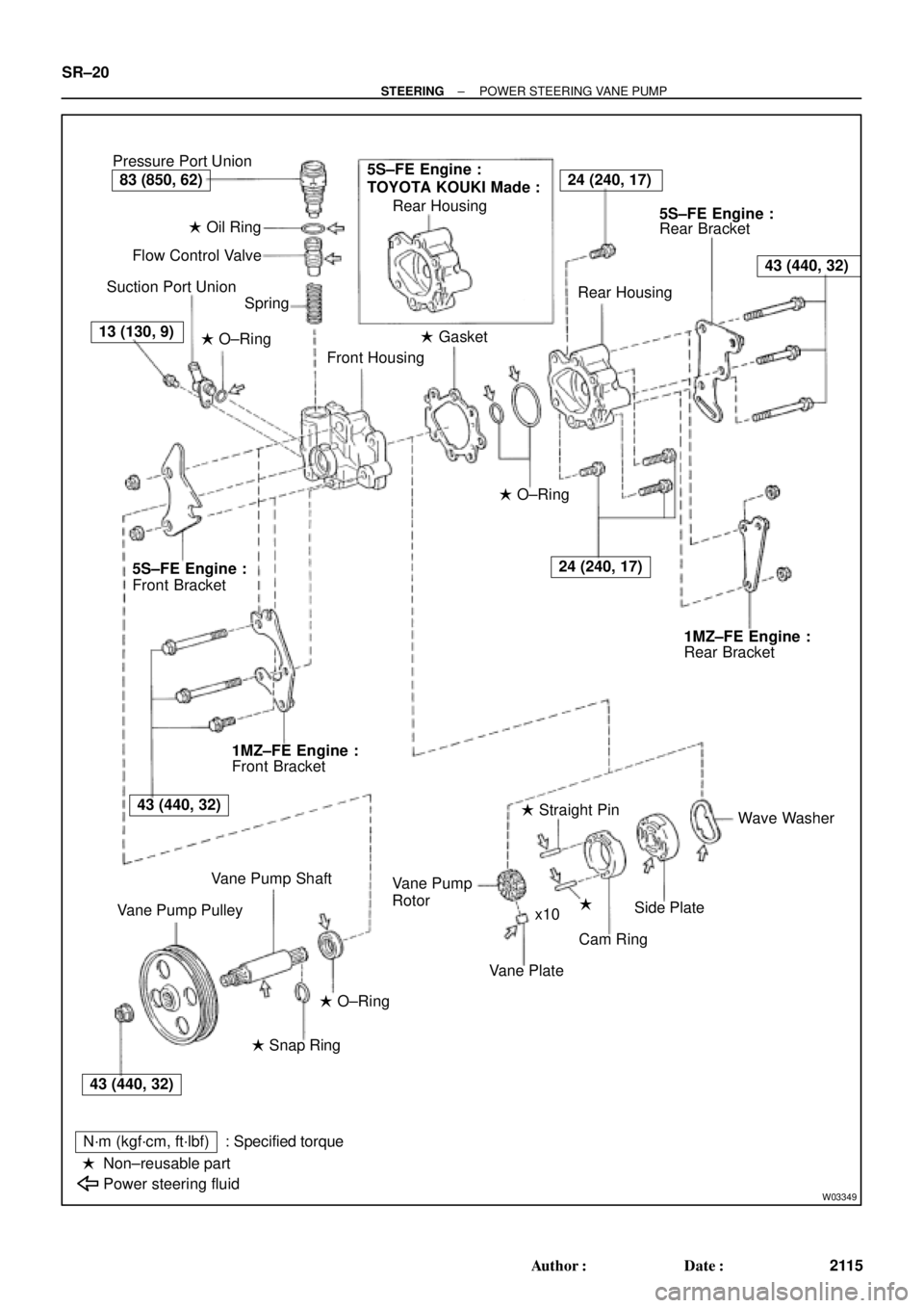
W03349
Pressure Port Union
� Oil Ring
Flow Control Valve
Suction Port Union
Spring
� O±Ring
Front Housing� Gasket Rear Housing
Rear Bracket
Rear Housing
� O±Ring
Rear Bracket
Wave Washer
�
Cam Ring � Straight Pin
Vane Plate Rotor
Side Plate Vane Pump
x10
� O±Ring
� Snap Ring
N´m (kgf´cm, ft´lbf)
Non±reusable part
Power steering fluid: Specified torque Vane Pump Shaft
Vane Pump PulleyFront Bracket Front Bracket
�
5S±FE Engine :
TOYOTA KOUKI Made :24 (240, 17)
43 (440, 32)
24 (240, 17)
83 (850, 62)
13 (130, 9)
5S±FE Engine :5S±FE Engine :
1MZ±FE Engine :1MZ±FE Engine :
43 (440, 32)
43 (440, 32) SR±20
± STEERINGPOWER STEERING VANE PUMP
2115 Author�: Date�:
Page 4311 of 4770

SR06O±01
W04220
5S±FE Engine :
1MZ±FE Engine :
Pressure
Feed TubeSST SST
W03360
Example 5S±FE Engine :
A
B
± STEERINGPOWER STEERING VANE PUMP
SR±21
2116 Author�: Date�:
REMOVAL
1. REMOVE FRONT FENDER APRON SEAL RH
Remove the 2 bolts.
2. DISCONNECT RETURN HOSE
NOTICE:
Take care not to spill fluid on the drive belt.
3. DISCONNECT PRESSURE FEED TUBE
(a) 5S±FE Engine:
Remove the clamp plate set bolt and nut.
(b) 5S±FE Engine:
Remove the 2 clamp plates and 2 holders from the tube.
(c) 5S±FE Engine:
Remove the clamp from the tube.
(d) 1MZ±FE Engine:
Remove the 2 clamp plate set nuts.
(e) 1MZ±FE Engine:
Remove the bolt.
(f) 1MZ±FE Engine:
Remove the 2 clamp plates and 2 holders from the tube.
(g) 5S±FE and 1MZ±FE Engines:
Using SST, disconnect the tube.
SST 09631±22020
4. REMOVE DRIVE BELT
Loosen the 2 (A and B) bolts.
5. REMOVE PS VANE PUMP ASSEMBLY WITH PRES-
SURE FEED TUBE
(a) Disconnect the connector from the oil pressure switch.
(b) Loosen bolt A sufficiently so that pump assembly can be
removed.
HINT:
Bolt A cannot be removed.
6. REMOVE PRESSURE FEED TUBE
(a) Remove the oil pressure switch from the union bolt.
NOTICE:
Be careful not to drop the switch.
If the switch is dropped or strongly damaged, replace it with a
new one.
(b) Remove the union bolt and gasket.
Page 4314 of 4770

R13897
Inscribed Mark
R11288
R07591
Compressed Air
R11563Inscribed Mark SR±24
± STEERINGPOWER STEERING VANE PUMP
2119 Author�: Date�:
5S±FE and 1MZ±FE Engines:
Inscribed mark: 1, 2, 3, 4 or None
HINT:
There are 5 vane lengths with the following rotor and cam ring
marks:
5S±FE and 1MZ±FE Engines:
Rotor and cam
ring markVane plate part
numberVane plate length
mm (in.)
None44345±2601014.999±15.001
(0.59051±0.59059)
144345±2602014.997±14.999
(0.59043±0.59051)
244345±2603014.995±14.997
(0.59035±0.59043)
344345±2604014.993±14.995
(0.59027±0.59035)
444345±2605014.991±14.993
(0.59020±0.59027)
3. INSPECT FLOW CONTROL VALVE
(a) Coat the valve with power steering fluid and check that it
falls smoothly into the valve hole by its own weight.
(b) Check the valve for leakage. Close one of the holes and
apply 392±490 kPa (4±5 kgf/cm
2, 57±71 psi) of com-
pressed air into the opposite side, and confirm that air
does not come out from the end holes.
If necessary, replace the valve with one having the same letter
as inscribed on the front housing.
5S±FE and 1MZ±FE Engines:
Inscribed mark: A, B, C, D, E or F
Page 4315 of 4770
R08702
Calipers
R11290
Vinyl Tape
W03541
Press
SST
Oil Seal
± STEERINGPOWER STEERING VANE PUMP
SR±25
2120 Author�: Date�:
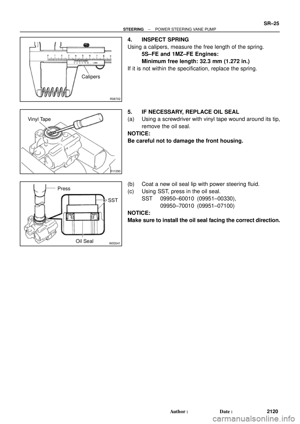
4. INSPECT SPRING
Using a calipers, measure the free length of the spring.
5S±FE and 1MZ±FE Engines:
Minimum free length: 32.3 mm (1.272 in.)
If it is not within the specification, replace the spring.
5. IF NECESSARY, REPLACE OIL SEAL
(a) Using a screwdriver with vinyl tape wound around its tip,
remove the oil seal.
NOTICE:
Be careful not to damage the front housing.
(b) Coat a new oil seal lip with power steering fluid.
(c) Using SST, press in the oil seal.
SST 09950±60010 (09951±00330),
09950±70010 (09951±07100)
NOTICE:
Make sure to install the oil seal facing the correct direction.
Page 4316 of 4770

SR06R±01
R13458
Inscribed Mark
R01149
Round End
R11292
SR±26
± STEERINGPOWER STEERING VANE PUMP
2121 Author�: Date�:
REASSEMBLY
NOTICE:
When using a vise, do not overtighten it.
1. COAT WITH POWER STEERING FLUID
(See page SR±18)
2. INSTALL VANE PUMP SHAFT
3. INSTALL STRAIGHT PINS
Using a plastic hammer, tap in 2 new pins.
NOTICE:
Be careful not to damage the pins.
4. INSTALL CAM RING
Align the holes of the ring and 2 straight pins, and install the ring
with the inscribed mark facing outward.
5. INSTALL VANE PUMP ROTOR
(a) Install the rotor with the inscribed mark facing outward.
(b) Install a new snap ring to the vane pump shaft.
6. INSTALL VANE PLATES
Install the 10 plates with the round end facing outward.
7. INSTALL GASKET
Install a new gasket.
8. INSTALL SIDE PLATE
Align the holes of the plate and 2 straight pins.
9. INSTALL WAVE WASHER
Install the washer so that its protrusions fit into the slots in the
side plate.
10. INSTALL REAR HOUSING
(a) Coat 2 new O±rings with power steering fluid and install
them to the housing.
(b) Torque the 4 bolts.
5S±FE and 1MZ±FE Engines:
Torque: 24 N´m (240 kgf´cm, 17 ft´lbf)
Page 4317 of 4770
W03339
Example 5S±FE Engine :
SST
± STEERINGPOWER STEERING VANE PUMP
SR±27
2122 Author�: Date�:
11. INSTALL SPRING, FLOW CONTROL VALVE AND
PRESSURE PORT UNION
(a) Install the valve facing the correct direction.
(See page SR±18)
(b) Coat a new O±ring with power steering fluid and install it
to the union.
(c) Torque the union.
5S±FE and 1MZ±FE Engines:
Torque: 83 N´m (850 kgf´cm, 62 ft´lbf)
12. INSTALL SUCTION PORT UNION
(a) Coat a new O±ring with power steering fluid and install it
to the union.
(b) Torque the bolt.
5S±FE and 1MZ±FE Engines:
Torque: 13 N´m (130 kgf´cm, 9 ft´lbf)
13. INSTALL FRONT AND REAR BRACKETS
Torque the 3 bolts and 2 nuts.
5S±FE and 1MZ±FE Engines:
Torque: 43 N´m (440 kgf´cm, 32 ft´lbf)
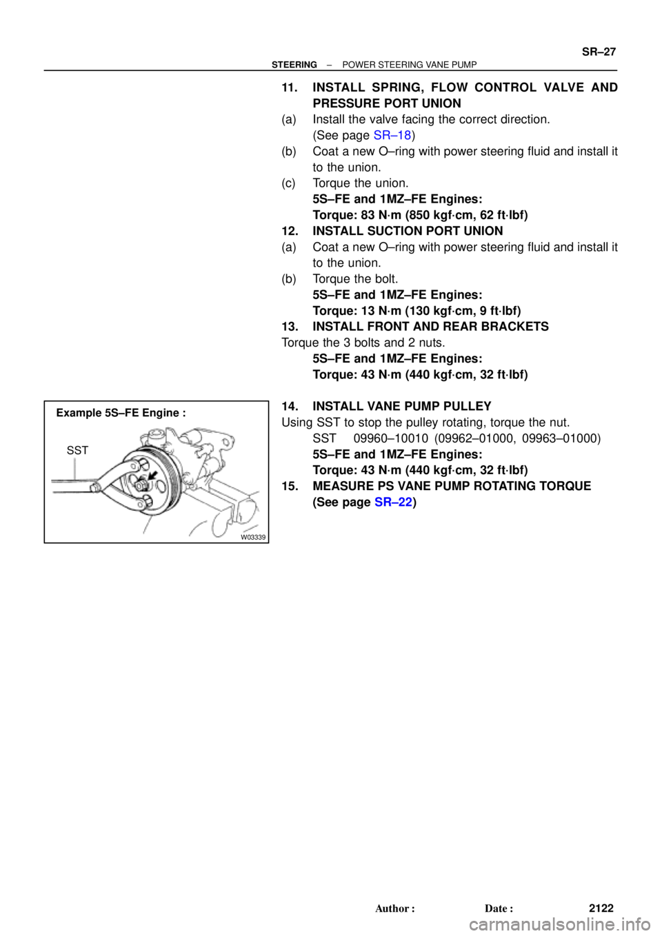
14. INSTALL VANE PUMP PULLEY
Using SST to stop the pulley rotating, torque the nut.
SST 09960±10010 (09962±01000, 09963±01000)
5S±FE and 1MZ±FE Engines:
Torque: 43 N´m (440 kgf´cm, 32 ft´lbf)
15. MEASURE PS VANE PUMP ROTATING TORQUE
(See page SR±22)
Page 4322 of 4770
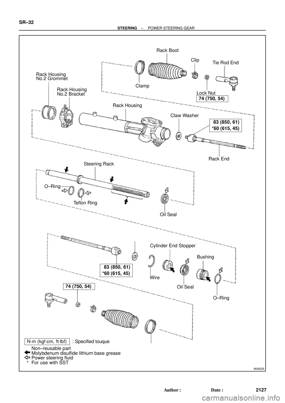
W04225
Rack Housing
No.2 Grommet
Rack Housing
No.2 Bracket
Rack Housing
� Claw Washer
Rack End Lock NutTie Rod End Rack Boot
� ClampClip
Steering Rack
� Teflon Ring
� Oil Seal
Cylinder End Stopper
Bushing
� O±Ring � Oil Seal � Wire �
�
N´m (kgf´cm, ft´lbf) : Specified touque
Power steering fluid
For use with SST Non±reusable part
Molybdenum disulfide lithium base grease �
*
74 (750, 54)
83 (850, 61)
*60 (615, 45)
83 (850, 61)
*60 (615, 45)
74 (750, 54)
� O±Ring SR±32
± STEERINGPOWER STEERING GEAR
2127 Author�: Date�: