Page 4323 of 4770
Z18921
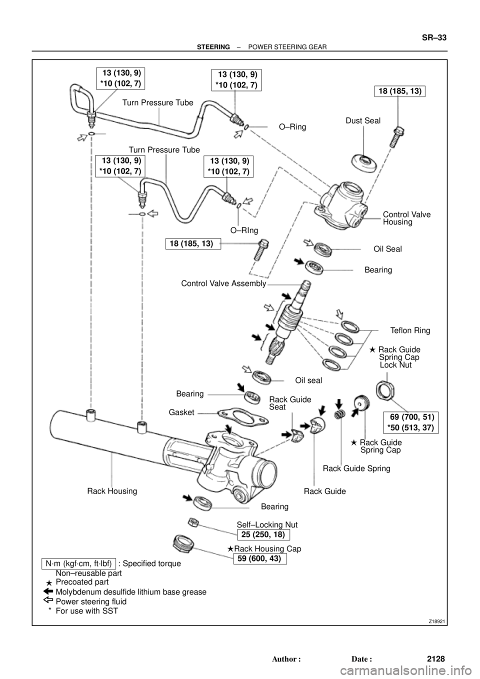
Turn Pressure Tube
� O±RingDust Seal
Turn Pressure Tube
� O±RIngControl Valve
Housing
� Oil Seal
� Bearing
� Teflon Ring
� Rack Guide
Spring Cap
Lock Nut
� Rack Guide
Spring Cap
Rack Guide Spring
Rack Guide
� Self±Locking Nut� Bearing
�Rack Housing Cap
N´m (kgf´cm, ft´lbf) : Specified torque
Non±reusable part
Precoated part
Molybdenum desulfide lithium base grease
Power steering fluid
For use with SSTRack Housing� Bearing
� GasketControl Valve Assembly � �
13 (130, 9)
*10 (102, 7) 13 (130, 9)
*10 (102, 7)
18 (185, 13)
69 (700, 51)
*50 (513, 37)
25 (250, 18)
59 (600, 43)
18 (185, 13)
13 (130, 9)
*10 (102, 7) 13 (130, 9)
*10 (102, 7)
�
�
*Rack Guide
Seat� Oil seal
± STEERINGPOWER STEERING GEAR
SR±33
2128 Author�: Date�:
Page 4329 of 4770

SR06W±01
R10072
Dial Indicator
F01792
Press
SST
Oil Seal
Bearing
W03560
Press
SST
SST Bearing
F01793
Press
SST
Bearing
F01794
Brass Bar
Bearing
± STEERINGPOWER STEERING GEAR
SR±39
2134 Author�: Date�:
INSPECTION
NOTICE:
When using a vise, do not overtighten it.
1. INSPECT STEERING RACK
(a) Using a dial indicator, check the rack for runout and for
teeth wear and damage.
Maximum runout: 0.03 mm (0.0118 in.)
(b) Check the back surface for wear and damage.
2. IF NECESSARY, REPLACE OIL SEAL AND BEARING
(a) Using SST, press out the oil seal and bearing from the
control valve housing.
SST 09950±60010 (09951±00250),
09950±70010 (09951±07200)
(b) Coat a new oil seal lip with power steering fluid.
(c) Using SST, press in the oil seal.
SST 09950±60010 (09951±00180, 09951±00320,
09952±06010), 09950±70010 (09951±07200)
NOTICE:
Make sure to install the oil seal facing the correct direction.
(d) Coat a new bearing with molybdenum disulfide lithium
base grease.
(e) Using SST, press in the bearing.
SST 09950±60010 (09951±00340),
09950±70010 (09951±07200)
3. IF NECESSARY, REPLACE 2 BEARINGS
(a) Using a brass bar and hammer, tap out the bearing from
the rack housing.
Page 4330 of 4770
 Usi")
F01795
Press
SST
Bearing
F01796
Bearing SST
Press
F01797
BearingSST Press
F01798Bushing SSTSST
Oil Seal
F01799
Press
Oil Seal
SST
SST
SR±40
± STEERINGPOWER STEERING GEAR
2135 Author�: Date�:
(b) Using SST, press out the bearing from the rack housing.
SST 09950±60010 (09951±00260),
09950±70010 (09951±07200)
(c) Coat a new bearing with molybdenum disulfide lithium
base grease.
(d) Using SST, press in the bearing.
SST 09950±60010 (09951±00310),
09950±70010 (09951±07200)
(e) Coat a new bearing with molybdenum disulfide lithium
base grease.
(f) Using SST, press in the bearing.
SST 09950±60010 (09951±00320),
09950±70010 (09951±07200)
4. IF NECESSARY, REPLACE OIL SEAL
(a) Using SST, remove the oil seal from the bushing.
SST 09527±20011, 09612±24014 (09613±22011)
NOTICE:
Be careful not to damage the bushing.
(b) Coat a new oil seal lip with power steering fluid.
(c) Using SST, press in the oil seal.
SST 09950±60010 (09951±00240, 09951±00400,
09952±06010)
NOTICE:
Make sure to install the oil seal facing the correct direction.
Page 4331 of 4770
 Using a screwdriver, remove the teflon ring and")
R10955
R06172
N00401
R11572
Teflon Ring
± STEERINGPOWER STEERING GEAR
SR±41
2136 Author�: Date�:
5. IF NECESSARY, REPLACE TEFLON RING AND O±
RING
(a) Using a screwdriver, remove the teflon ring and O±ring
from the steering rack.
NOTICE:
Be careful not to damage the groove for the teflon ring.
(b) Coat a new O±ring with power steering fluid and install it.
(c) Expand a new teflon ring with your fingers.
NOTICE:
Be careful not to over±expand the ring.
(d) Coat the ring with power steering fluid.
(e) Install the ring to the steering rack, and settle it down with
your fingers.
6. IF NECESSARY, REPLACE TEFLON RINGS
(a) Using a screwdriver, remove the 4 rings from the control
valve assembly.
NOTICE:
Be careful not to damage the grooves for the teflon ring.
(b) Expand 4 new teflon rings with your fingers.
NOTICE:
Be careful not to over±expand the teflon ring.
(c) Coat the rings with power steering fluid.
(d) Install the rings to the control valve assembly, and settle
them down with your fingers.
Page 4333 of 4770

SR06X±01
W03561
Press
SST
SST
Oil Seal
W02101
SST Rack Teeth End
R11574
Vinyl Tape
± STEERINGPOWER STEERING GEAR
SR±43
2138 Author�: Date�:
REASSEMBLY
NOTICE:
When using a vise, do not overtighten it.
1. COAT WITH POWER STEERING FLUID OR MOLYBDE-
NUM DISULFIDE LITHIUM BASE GREASE
(See pages SR±31)
2. INSTALL OIL SEAL
(a) Coat a new oil seal lip with power steering fluid.
(b) Using SST, press in the oil seal.
SST 09950±60010 (09951±00240, 09951±00430,
09952±06010), 09950±70010 (09951±07360)
NOTICE:
�Make sure to install the oil seal facing the correct
direction.
�Take care that the oil seal does not get reversed as
you install it.
3. INSTALL STEERING RACK
(a) Install SST to the rack.
SST 09631±33010
HINT:
If necessary, scrape the burrs off the rack teeth end and bur-
nish.
(b) Coat the SST with power steering fluid.
(c) Install the rack into the rack housing.
NOTICE:
Be careful not to damage the oil seal lip.
(d) Remove SST.
4. INSTALL BUSHING
(a) Coat a new O±ring with power steering fluid and install it
to the bushing.
(b) To prevent oil seal lip damage, wind vinyl tape on the
steering rack end, and apply power steering fluid.
(c) Install the bushing.
NOTICE:
�Make sure to install the bushing facing the correct
direction.
�Be careful not to damage the oil seal lip.
Page 4334 of 4770
 Align the installation ho")
R11656
SST
Wire
Cylinder End
Stopper
R00662
SST
R11657
R11658
R11575
Vinyl Tape SR±44
± STEERINGPOWER STEERING GEAR
2139 Author�: Date�:
5. INSTALL CYLINDER END STOPPER
(a) Align the installation hole for the wire of the stopper with
the slot of the rack housing.
(b) Install a new wire into the stopper.
(c) Using SST, turn the stopper clockwise 450 ± 50°.
SST 09631±10021
6. AIR TIGHTNESS TEST
(a) Install SST to the rack housing.
SST 09631±12071
(b) Apply 53 kPa (400 mmHg, 15.75 in.Hg) of vacuum for
about 30 seconds.
(c) Check that there is no change in the vacuum.
If there is change in the vacuum, check the installation of the oil
seals.
7. INSTALL RACK HOUSING NO.2 BRACKET AND
GROMMET
(a) Install the grommet to the bracket.
HINT:
Align the projection of the grommet with the hole of the bracket.
(b) Align the matchmarks on the bracket and rack housing.
(c) Place the bracket in a vise and tighten the vise to fasten
the clamp.
8. INSTALL CONTROL VALVE ASSEMBLY
(a) To prevent oil seal lip damage, wind vinyl tape on the ser-
rated part of the valve shaft.
(b) Coat the teflon rings with power steering fluid.
(c) Install the valve assembly into the valve housing.
NOTICE:
Be careful not to damage the teflon rings and oil seal.
Page 4335 of 4770
 Coat a new oil seal lip with power steering fluid.
(b) Using SST, pr")
W03562Oil Seal SST Press
R11648
SST
R11659
Punch
± STEERINGPOWER STEERING GEAR
SR±45
2140 Author�: Date�:
9. INSTALL OIL SEAL
(a) Coat a new oil seal lip with power steering fluid.
(b) Using SST, press in the oil seal.
SST 09612±22011
NOTICE:
Make sure to install the oil seal facing the correct direction.
10. INSTALL CONTROL VALVE HOUSING WITH CON-
TROL VALVE ASSEMBLY
(a) Place a new gasket on the rack housing.
(b) Align the matchmarks on the valve housing and rack
housing.
(c) Torque the 2 bolts.
Torque: 18 N´m (185 kgf´cm, 13 ft´lbf)
11. INSTALL SELF±LOCKING NUT
Using SST to stop the control valve shaft rotating, torque a new
nut.
SST 09616±00010
Torque: 25 N´m (250 kgf´cm, 18 ft´lbf)
12. INSTALL DUST COVER
13. INSTALL RACK HOUSING CAP
(a) Apply sealant to 2 or 3 threads of the cap.
Sealant:
Part No.08833±00080, THREE BOND 1344,
LOCTITE 242 or equivalent
(b) Torque the cap.
Torque: 59 N´m (600 kgf´cm, 43 ft´lbf)
(c) Using a punch and hammer, stake the 2 parts of the cap.
14. INSTALL RACK GUIDE SEAT, RACK GUIDE, RACK
GUIDE SPRING AND RACK GUIDE SPRING CAP
(a) Install the seat to the guide.
(b) Apply sealant to 2 or 3 threads of the cap.
Sealant:
Part No.08833±00080, THREE BOND 1344,
LOCTITE 242 or equivalent
(c) Temporarily install the cap.
Page 4338 of 4770

or less
SST
W04231
Fulcrum
LengthSST SR±48
± STEERINGPOWER STEERING GEAR
2143 Author�: Date�:
18. INSTALL RH AND LH RACK BOOTS, CLAMPS AND
CLIPS
(a) Ensure that the ste")
R11669
W04223
2 mm
(0.79 in.)
or less
SST
W04231
Fulcrum
LengthSST SR±48
± STEERINGPOWER STEERING GEAR
2143 Author�: Date�:
18. INSTALL RH AND LH RACK BOOTS, CLAMPS AND
CLIPS
(a) Ensure that the steering rack hole is not clogged with
grease.
HINT:
If the hole is clogged, the pressure inside the boot will change
after it is assembled and the steering wheel is turned.
(b) Install the boot.
NOTICE:
Be careful not to damage or twist the boot.
(c) Using SST, tighten the clamp as shown in the illustration.
SST 09521±24010
19. INSTALL RH AND LH TIE ROD ENDS AND LOCK NUTS
(a) Screw the lock nut and tie rod end onto the rack end until
the matchmarks are aligned.
(b) After adjusting toe±in, torque the nut.
(See page SA±4)
Torque: 74 N´m (750 kgf´cm, 54 ft´lbf)
20. INSTALL 2 TURN PRESSURE TUBES
(a) Coat 2 new O±rings with power steering fluid and install
them to the tube.
(b) Using SST, install the tube.
SST 09633±00020
Torque: 10 N´m (102 kgf´cm, 7 ft´lbf)
HINT:
�Use a torque wrench with a fulcrum length of 250 mm
(9.84 in.).
�This torque value is effective in case that SST is parallel
to a torque wrench.