Page 4344 of 4770

W03085
Front
R03030
Rear
SA079±01
Z03382
SA3213
AB
C D
Front SA±4
± SUSPENSION AND AXLEFRONT WHEEL ALIGNMENT
1955 Author�: Date�:
FRONT WHEEL ALIGNMENT
INSPECTION
1. MEASURE VEHICLE HEIGHT
Tire sizeFront*1 mm (in.)Rear*2 mm (in.)
195/70R14212 (8.35)264 (10.39)
205/65R15215 (8.46)266 (10.49)
*1: Front measuring point
Measure from the ground to the center of the front side lower
suspension arm mounting bolt.
*
2: Rear measuring point
Measure from the ground to the center of the strut rod mounting
bolt.
NOTICE:
Before inspecting the wheel alignment, adjust the vehicle
height to the specification.
If the vehicle height is not within the specification, try to adjust
it by pushing down on or lifting the body.
2. INSTALL CAMBER±CASTER±KINGPIN GAUGE
ONTO VEHICLE OR POSITION VEHICLE ON WHEEL
ALIGNMENT TESTER
Follow the specific instructions of the equipment manufacturer.
3. INSPECT CAMBER, CASTER AND STEERING AXIS
INCLINATION
5S±FE1MZ±FE
Camber
Left±right error±0°36' ± 45'
(±0.6° ± 0.75°)
45' (0.75°) or less±0°37' ± 45'
(±0.62° ± 0.75°)
45' (0.75°) or less
Caster
Left±right error2°10' ± 45'
(2.17° ± 0.75°)
45' (0.75°) or less2°11' ± 45'
(2.18° ± 0.75°)
45' (0.75°) or less
Steering axis inclination
Left±right error13°01' ± 45'
(13.02° ± 0.75°)
45' (0.75°) or less13°04' ± 45'
(13.07° ± 0.75°)
45' (0.75°) or less
HINT:
If the caster and steering axis inclination are not within the spec-
ification, after the camber has correctly adjusted, recheck the
suspension parts for damaged and/or worn out parts.
4. INSPECT TOE±IN
Toe±in
(Total)A + B: 0° ± 12' (0° ± 0.2°)
C ± D: 0 ± 2 mm (0 ± 0.08 in.)
If the toe±in is not within the specification, adjust it at the rack
ends.
Page 4346 of 4770
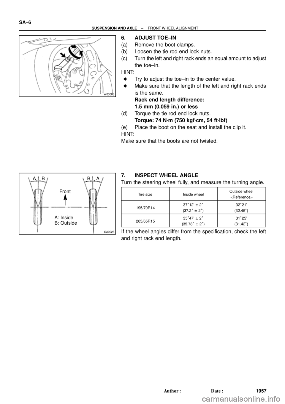
W03088
SA0028
A: Inside
B: Outside AB
Front BA SA±6
± SUSPENSION AND AXLEFRONT WHEEL ALIGNMENT
1957 Author�: Date�:
6. ADJUST TOE±IN
(a) Remove the boot clamps.
(b) Loosen the tie rod end lock nuts.
(c) Turn the left and right rack ends an equal amount to adjust
the toe±in.
HINT:
�Try to adjust the toe±in to the center value.
�Make sure that the length of the left and right rack ends
is the same.
Rack end length difference:
1.5 mm (0.059 in.) or less
(d) Torque the tie rod end lock nuts.
Torque: 74 N´m (750 kgf´cm, 54 ft´lbf)
(e) Place the boot on the seat and install the clip it.
HINT:
Make sure that the boots are not twisted.
7. INSPECT WHEEL ANGLE
Turn the steering wheel fully, and measure the turning angle.
Tire sizeInside wheelOutside wheel
195/70R1437°12' ± 2°
(37.2° ± 2°)32°21'
(32.45°)
205/65R1535°47' ± 2°
(35.78° ± 2°)31°25'
(31.42°)
If the wheel angles differ from the specification, check the left
and right rack end length.
Page 4350 of 4770

2. CHECK BE")
SA07C±01
W03084W03084
W03093
W03139
W03094
SST
SA±10
± SUSPENSION AND AXLEFRONT AXLE HUB
1961 Author�: Date�:
REMOVAL
1. REMOVE FRONT WHEEL
Torque: 103 N´m (1,050 kgf´cm, 76 ft´lbf)
2. CHECK BEARING BACKLASH AND AXLE HUB DEVI-
ATION
(a) Remove the 2 bolts, brake caliper and disc.
(b) Support the brake caliper securely.
(c) Using a dial indicator near the center of the axle hub and
check the backlash in the bearing shaft direction.
Maximum: 0.05 mm (0.0020 in.)
If the backlash exceeds the maximum, replace the bearing.
(d) Using a dial indicator, check the deviation at the surface
of the axle hub outside the hub bolt.
Maximum: 0.05 mm (0.0020 in.)
If the deviation exceeds the maximum, replace the bearing.
(e) Install the disc, 2 bolts and brake caliper.
Torque: 107 N´m (1,090 kgf´cm, 79 ft´lbf)
3. REMOVE DRIVE SHAFT LOCK NUT
(a) Remove the cotter pin and lock cap.
(b) With applying the brakes, remove the nut.
Torque: 294 N´m (3,000 kgf´cm, 217 ft´lbf)
(c) Remove the brake caliper and disc.
4. w/ ABS:
REMOVE ABS SPEED SENSOR AND WIRE HARNESS
CLAMP
Torque: 8.0 N´m (82 kgf´cm, 71 in.´lbf)
5. LOOSEN 2 NUTS ON LOWER SIDE OF SHOCK AB-
SORBER
Torque: 211 N´m (2,150 kgf´cm, 156 ft´lbf)
HINT:
�Do not remove the bolts.
�At the time of installation, coat the nut's thread with en-
gine oil.
6. DISCONNECT TIE ROD END FROM STEERING
KNUCKLE
(a) Remove the cotter pin and nut.
Torque: 49 N´m (500 kgf´cm, 36 ft´lbf)
(b) Using SST, disconnect the tie rod end from the steering
knuckle.
SST 09610±20012
Page 4357 of 4770

SA±17
1968 Author�: Date�:
REMOVAL
NOTICE:
The hub bearing could be damaged if it is subjected to the
vehicle weig")
SA08Q±01
FA1535
SST
W03093
W03142
± SUSPENSION AND AXLEFRONT DRIVE SHAFT (5S±FE)
SA±17
1968 Author�: Date�:
REMOVAL
NOTICE:
The hub bearing could be damaged if it is subjected to the
vehicle weight, such as when moving the vehicle with the
drive shaft removed.
Therefore, if it is absolutely necessary to place the vehicle
weight on the hub bearing, first support it with SST.
SST 09608±16042 (09608±02021, 09608±02041)
1. REMOVE FRONT WHEEL AND FRONT FENDER
APRON SEAL
Torque: 103 N´m (1,050 kgf´cm, 76 ft´lbf)
2. REMOVE DRIVE SHAFT LOCK NUT
(a) Remove the cotter pin and lock cap.
(b) With applying the brakes, remove the nut.
Torque: 294 N´m (3,000 kgf´cm, 217 ft´lbf)
3. DRAIN GEAR OIL (M/T) or ATF (A/T)
4. DISCONNECT TIE ROD END FROM STEERING
KNUCKLE (See page SA±10)
5. DISCONNECT LOWER BALL JOINT FROM LOWER
SUSPENSION ARM (See page SA±10)
6. DISCONNECT DRIVE SHAFT FROM AXLE HUB
(a) Using a plastic hammer, disconnect the drive shaft from
the axle hub.
NOTICE:
Cover the drive shaft boot with cloth to protect it from dam-
age.
(b) Push the front axle hub toward the outside of the vehicle,
and separate the drive shaft from the axle hub.
Page 4374 of 4770

2. REMOVE FLEXIBLE HOSE AN")
SA07N±01
Z19346
To Outside SA±34
± SUSPENSION AND AXLEFRONT SHOCK ABSORBER
1985 Author�: Date�:
REMOVAL
1. REMOVE FRONT WHEEL
Torque: 103 N´m (1,050 kgf´cm, 76 ft´lbf)
2. REMOVE FLEXIBLE HOSE AND ABS SPEED SEN-
SOR WIRE HARNESS (w/ ABS) AND CLAMP FROM
SHOCK ABSORBER
Remove the bolt, flexible hose and ABS wire harness clamp.
Torque: 29 N´m (300 kgf´cm, 22 ft´lbf)
3. DISCONNECT STABILIZER BAR LINK FROM SHOCK
ABSORBER (See page SA±48)
4. DISCONNECT SHOCK ABSORBER FROM STEERING
KNUCKLE
(a) Remove the 2 nuts and bolts on the lower side of the
shock absorber.
Torque: 211 N´m (2,150 kgf´cm, 156 ft´lbf)
(b) Remove the shock absorber from the steering knuckle.
HINT:
At the time of installation, coat the nut's threads with engine oil.
5. REMOVE SHOCK ABSORBER WITH COIL SPRING
Remove the 3 nuts, suspension support No.2 and shock ab-
sorber with the coil spring.
Torque: 80 N´m (820 kgf´cm, 59 ft´lbf)
HINT:
At the time of installation rotate the suspension support and set
it in the direction, as shown in the illustration.
Page 4386 of 4770
SA080±01
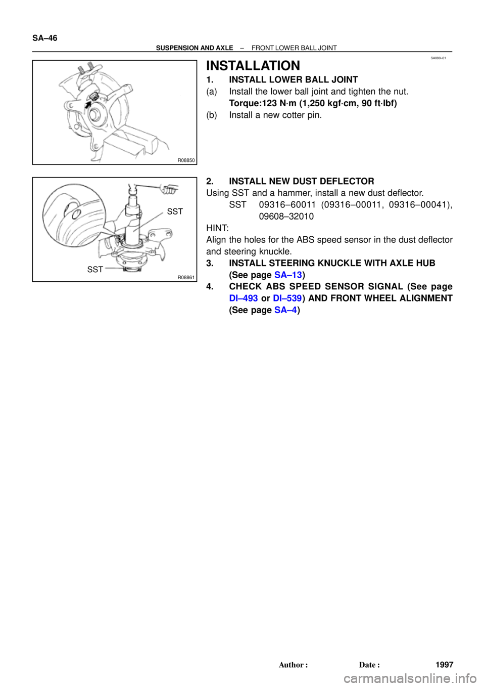
R08850
R08861
SST
SST SA±46
± SUSPENSION AND AXLEFRONT LOWER BALL JOINT
1997 Author�: Date�:
INSTALLATION
1. INSTALL LOWER BALL JOINT
(a) Install the lower ball joint and tighten the nut.
Torque:123 N´m (1,250 kgf´cm, 90 ft´lbf)
(b) Install a new cotter pin.
2. INSTALL NEW DUST DEFLECTOR
Using SST and a hammer, install a new dust deflector.
SST 09316±60011 (09316±00011, 09316±00041),
09608±32010
HINT:
Align the holes for the ABS speed sensor in the dust deflector
and steering knuckle.
3. INSTALL STEERING KNUCKLE WITH AXLE HUB
(See page SA±13)
4. CHECK ABS SPEED SENSOR SIGNAL (See page
DI±493 or DI±539) AND FRONT WHEEL ALIGNMENT
(See page SA±4)
Page 4413 of 4770

REMOVAL
1. REMOVE S")
SR06I±05
F00879
Torx Screw
Screw Case
F00878
Airbag Connector
Correct Wrong
W03302
Matchmarks
SST
± STEERINGTILT STEERING COLUMN
SR±11
2096 Author�: Date�:
2001 CAMRY (RM819U)
REMOVAL
1. REMOVE STEERING WHEEL PAD
NOTICE:
If the airbag connector is disconnected with the ignition
switch at ON or ACC, DTCs will be recorded.
(a) Place the front wheels facing straight ahead.
(b) Remove the 2 steering wheel lower No.2 and No.3 cov-
ers.
(c) Using a torx socket wrench, loosen the 2 torx screws.
HINT:
Loosen the 2 screws until the groove along the screw circumfer-
ence catches on the screw case.
(d) Pull the pad out from the steering wheel and disconnect
the airbag connector.
CAUTION:
�When storing the wheel pad, keep the upper surface
of the pad facing upward.
�Never disassemble the wheel pad.
NOTICE:
When removing the wheel pad, take care not to pull the air-
bag wire harness.
2. REMOVE STEERING WHEEL
(a) Disconnect the connector.
(b) Remove the steering wheel set nut.
(c) Place matchmarks on the steering wheel and main shaft
assembly.
(d) Using SST, remove the wheel.
SST 09950±50012 (09951±05010, 09952±05010,
09953±05020, 09954±05020)
Page 4515 of 4770
BRAKE DISC ANTI±RUST COVER REMOVAL (CONT'D)Page 2 of 2
RECOMMENDED REMOVAL PROCEDURE:
Turn the right front wheel to full right lock.
Unhook the Anti±Rust Cover from the disc brake dust cover, then pull the center of the Anti±Rust
Cover toward the wheel. This separates the Anti±Rust Cover from the disc brake dust cover (see
illustration below).
Pull the center of the Anti±Rust Cover by hand towards you to break the thin portion of cover.
Remove the Anti±Rust Cover along the arch of the wheel disc by shaking it up and down. If the
cover is torn while removing, check to see that no parts of the cover are left inside.
Turn the steering wheel to full left lock and perform the same steps on the left front wheel. If
applicable, also remove the Anti±Rust Covers on the rear brakes.
Indicate on the new car inspection sheet that the Anti±Rust Covers have been removed.
Page 2 of 2
RECOMMENDED REMOVAL PROCEDURE:
Turn the right front wheel to full right lock.
Unhook the Anti±Rust Cover from the disc brake dust cover, then p")