Page 4306 of 4770
 Torque the 4 column assembly set nuts.
Torque:")
SR06M±01
W03303
Matchmarks
W02655
Mark SR±16
± STEERINGTILT STEERING COLUMN
2111 Author�: Date�:
INSTALLATION
1. INSTALL STEERING COLUMN ASSEMBLY
(a) Torque the 4 column assembly set nuts.
Torque: 25 N´m (260 kgf´cm, 19 ft´lbf)
(b) Connect the connectors.
2. INSTALL INTERMEDIATE SHAFT ASSEMBLY
Torque the bolt.
Torque: 35 N´m (360 kgf´cm, 26 ft´lbf)
3. CONNECT INTERMEDIATE SHAFT ASSEMBLY
(a) Align the matchmarks on the intermediate shaft and con-
trol valve shaft.
(b) Torque the bolt.
Torque: 35 N´m (360 kgf´cm, 26 ft´lbf)
4. INSTALL SPIRAL CABLE
(See page BE±23)
5. INSTALL COMBINATION SWITCH WITH SPIRAL
CABLE
(a) Tighten the 3 screws.
(b) Connect the airbag connector.
(c) Connect the 3 connectors.
6. INSTALL LOWER INSTRUMENT FINISH PANEL
7. INSTALL LH LOWER INSTRUMENT PANEL
Tighten the 4 bolts.
8. INSTALL No.1 LOWER INSTRUMENT PANEL
(a) Connect the hood lock control cable.
(b) Tighten the 2 screws.
9. INSTALL COWL SIDE TRIM
Install the clip.
10. INSTALL FRONT DOOR INSIDE SCUFF PLATE
11. INSTALL UPPER AND LOWER COLUMN COVERS
(a) Tighten the 3 screws.
(b) Install the lower No.2 cover to the lower cover.
12. CENTER SPIRAL CABLE
(a) Check that the front wheels are facing straight ahead.
(b) Turn the cable counterclockwise by hand until it becomes
harder to turn the cable.
(c) Then rotate the cable clockwise about 3 turns to align the
mark.
HINT:
The cable will rotate about 3 turns to either left or right of the
center.
Page 4307 of 4770
W03304
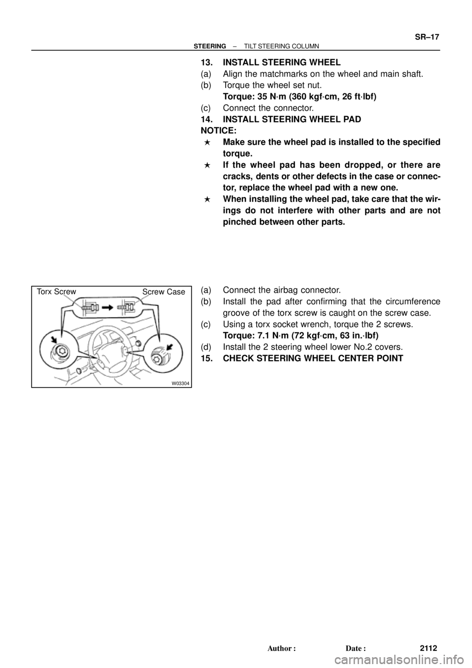
Torx Screw
Screw Case
± STEERINGTILT STEERING COLUMN
SR±17
2112 Author�: Date�:
13. INSTALL STEERING WHEEL
(a) Align the matchmarks on the wheel and main shaft.
(b) Torque the wheel set nut.
Torque: 35 N´m (360 kgf´cm, 26 ft´lbf)
(c) Connect the connector.
14. INSTALL STEERING WHEEL PAD
NOTICE:
�Make sure the wheel pad is installed to the specified
torque.
�If the wheel pad has been dropped, or there are
cracks, dents or other defects in the case or connec-
tor, replace the wheel pad with a new one.
�When installing the wheel pad, take care that the wir-
ings do not interfere with other parts and are not
pinched between other parts.
(a) Connect the airbag connector.
(b) Install the pad after confirming that the circumference
groove of the torx screw is caught on the screw case.
(c) Using a torx socket wrench, torque the 2 screws.
Torque: 7.1 N´m (72 kgf´cm, 63 in.´lbf)
(d) Install the 2 steering wheel lower No.2 covers.
15. CHECK STEERING WHEEL CENTER POINT
Page 4324 of 4770
SR06U±01
W04222
SST SR±34
± STEERINGPOWER STEERING GEAR
2129 Author�: Date�:
REMOVAL
1. PLACE FRONT WHEELS FACING STRAIGHT AHEAD
2. REMOVE STEERING WHEEL PAD
(See page SR±11)
3. REMOVE STEERING WHEEL
(See page SR±11)
4. DISCONNECT RH AND LH TIE ROD ENDS
(See page SA±10)
5. DISCONNECT INTERMEDIATE SHAFT ASSEMBLY
(See page SR±11)
6. DISCONNECT CLAMP PLATE
Remove the nut.
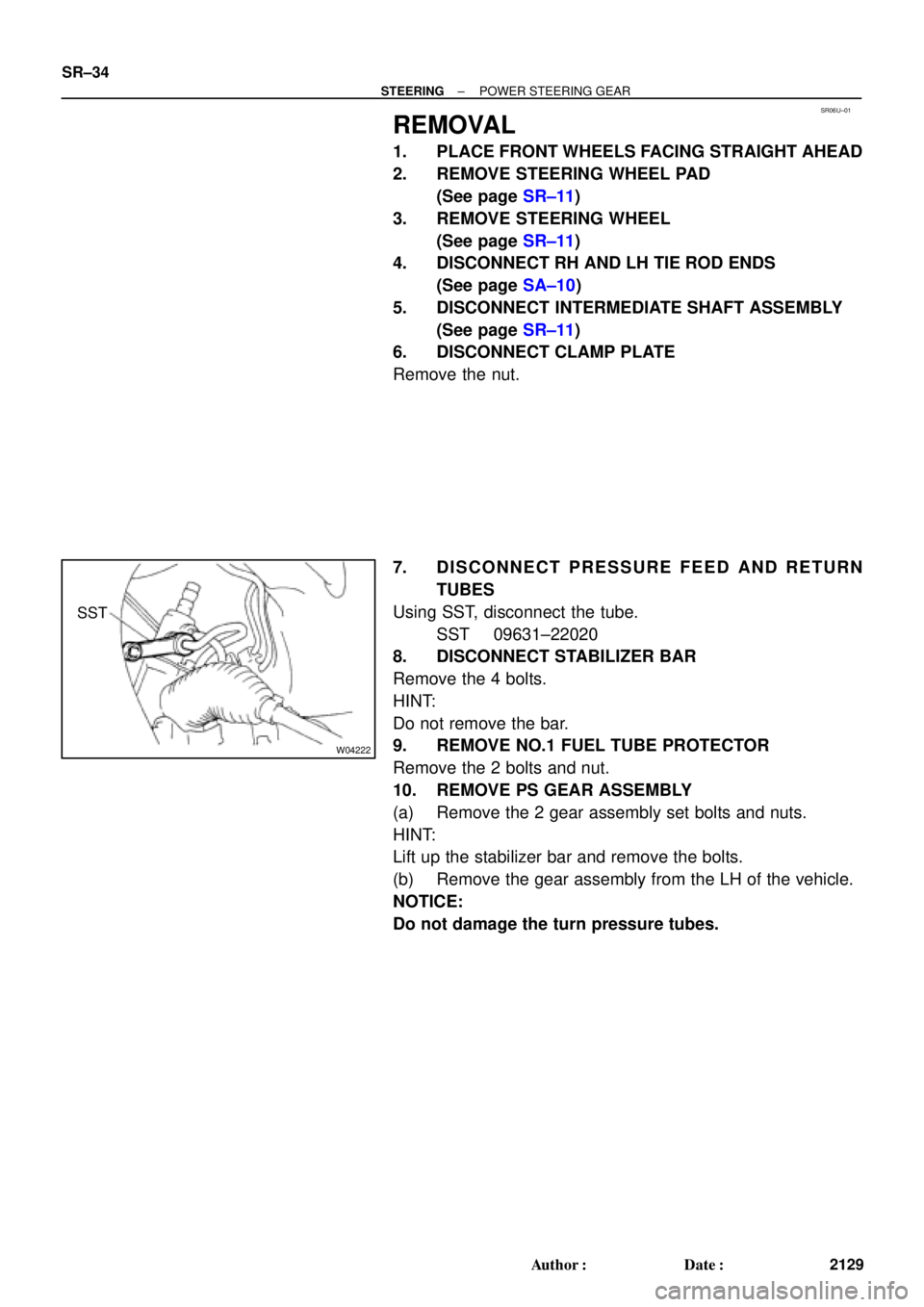
7. DISCONNECT PRESSURE FEED AND RETURN
TUBES
Using SST, disconnect the tube.
SST 09631±22020
8. DISCONNECT STABILIZER BAR
Remove the 4 bolts.
HINT:
Do not remove the bar.
9. REMOVE NO.1 FUEL TUBE PROTECTOR
Remove the 2 bolts and nut.
10. REMOVE PS GEAR ASSEMBLY
(a) Remove the 2 gear assembly set bolts and nuts.
HINT:
Lift up the stabilizer bar and remove the bolts.
(b) Remove the gear assembly from the LH of the vehicle.
NOTICE:
Do not damage the turn pressure tubes.
Page 4338 of 4770

or less
SST
W04231
Fulcrum
LengthSST SR±48
± STEERINGPOWER STEERING GEAR
2143 Author�: Date�:
18. INSTALL RH AND LH RACK BOOTS, CLAMPS AND
CLIPS
(a) Ensure that the ste")
R11669
W04223
2 mm
(0.79 in.)
or less
SST
W04231
Fulcrum
LengthSST SR±48
± STEERINGPOWER STEERING GEAR
2143 Author�: Date�:
18. INSTALL RH AND LH RACK BOOTS, CLAMPS AND
CLIPS
(a) Ensure that the steering rack hole is not clogged with
grease.
HINT:
If the hole is clogged, the pressure inside the boot will change
after it is assembled and the steering wheel is turned.
(b) Install the boot.
NOTICE:
Be careful not to damage or twist the boot.
(c) Using SST, tighten the clamp as shown in the illustration.
SST 09521±24010
19. INSTALL RH AND LH TIE ROD ENDS AND LOCK NUTS
(a) Screw the lock nut and tie rod end onto the rack end until
the matchmarks are aligned.
(b) After adjusting toe±in, torque the nut.
(See page SA±4)
Torque: 74 N´m (750 kgf´cm, 54 ft´lbf)
20. INSTALL 2 TURN PRESSURE TUBES
(a) Coat 2 new O±rings with power steering fluid and install
them to the tube.
(b) Using SST, install the tube.
SST 09633±00020
Torque: 10 N´m (102 kgf´cm, 7 ft´lbf)
HINT:
�Use a torque wrench with a fulcrum length of 250 mm
(9.84 in.).
�This torque value is effective in case that SST is parallel
to a torque wrench.
Page 4339 of 4770
 Install the gear assembly from the LH of the vehicle.
NOTICE")
SR06Y±01
W04224
SST
Fulcrum
Length
± STEERINGPOWER STEERING GEAR
SR±49
2144 Author�: Date�:
INSTALLATION
1. INSTALL PS GEAR ASSEMBLY
(a) Install the gear assembly from the LH of the vehicle.
NOTICE:
Do not damage the turn pressure tubes.
(b) Torque the 2 gear assembly set bolts and nuts.
Torque: 181 N´m (1,850 kgf´cm, 134 ft´lbf)
HINT:
Lift up the stabilizer bar and install the bolts.
2. INSTALL NO.1 FUEL TUBE PROTECTOR
Install the 2 bolts and nut.
3. CONNECT STABILIZER BAR
Torque the 4 bolts.
Torque: 19 N´m (195 kgf´cm, 14 ft´lbf)
4. CONNECT PRESSURE FEED AND RETURN TUBES
Using SST, connect the tube.
SST 09631±22020
Torque: 32 N´m (326 kgf´cm, 24 ft´lbf)
HINT:
�Use a torque wrench with a fulcrum length of 300 mm
(11.81 in.).
�This torque value is effective in case that SST is parallel
to a torque wrench.
5. CONNECT CLAMP PLATE
Torque the nut.
Torque: 10 N´m (100 kgf´cm, 7 ft´lbf)
6. CONNECT INTERMEDIATE SHAFT ASSEMBLY
(See page SR±16)
7. CONNECT RH AND LH TIE ROD ENDS
(See page SA±10)
8. POSITION FRONT WHEELS FACING STRAIGHT
AHEAD
HINT:
Do it with the front of the vehicle jacked up.
9. CENTER SPIRAL CABLE
(See page SR±16)
10. INSTALL STEERING WHEEL
(a) Install the wheel at straight±ahead position.
(b) Temporarily tighten the wheel set nut.
(c) Connect the connector.
11. BLEED POWER STEERING SYSTEM
(See page SR±4)
12. CHECK STEERING WHEEL CENTER POINT
Page 4340 of 4770
SR±50
± STEERINGPOWER STEERING GEAR
2145 Author�: Date�:
13. TORQUE STEERING WHEEL SET NUT
Torque: 35 N´m (360 kgf´cm, 26 ft´lbf)
14. INSTALL STEERING WHEEL PAD
(See page SR±16)
15. CHECK FRONT WHEEL ALIGNMENT
(See page SA±4)
Page 4341 of 4770

SA077±01
± SUSPENSION AND AXLETROUBLESHOOTING
SA±1
1952 Author�: Date�:
TROUBLESHOOTING
PROBLEM SYMPTOMS TABLE
Use the table below to help you find the cause of the problem. The numbers indicate the priority of the likely
cause of the problem. Check each part in order. If necessary, replace these parts.
SymptomSuspect AreaSee page
Wander/pulls
1. Tire (Worn or improperly inflated)
2. Wheel alignment (Incorrect)
3. Steering linkage (Loosen or worn)
4. Hub bearings (Worn)
5. Suspension parts (Worn)
6. Steering gear (Out of adjustment or broken)SA±2
SA±4
SA±7
±
SA±10
±
±
Bottoming
1. Vehicle (Overloaded)
2. Spring (Weak)
3. Shock absorber (Worn)±
SA±33
SA±56
SA±33
SA±56
Sways/pitches
1. Tire (Worn or improperly inflated)
2. Stabilizer bar (Bent or broken)
3. Shock absorber (Worn)SA±2
SA±47
SA±69
SA±33
SA±56
Front wheel shimmy
1. Tire (Worn or improperly inflated)
2. Wheels (Out of balance)
3. Shock absorber (Worn)
4. Wheel alignment (Incorrect)
5. Ball joints (Worn)
6. Hub bearings (Worn)
7. Steering linkage (Loosen or worn)
8. Steering gear (Out of adjustment or broken)SA±2
SA±2
SA±33
SA±56
SA±4
SA±7
SA±43
SA±10
±
±
Abnormal tire wear
1. Tire (Worn or improperly inflated)
2. Wheels (Out of balance)
3. Suspension parts (Worn)
4. Shock absorber (Worn)SA±2
SA±2
±
SA±33
SA±56
Page 4343 of 4770
W03084
± SUSPENSION AND AXLETIRE AND WHEEL
SA±3
1954 Author�: Date�:
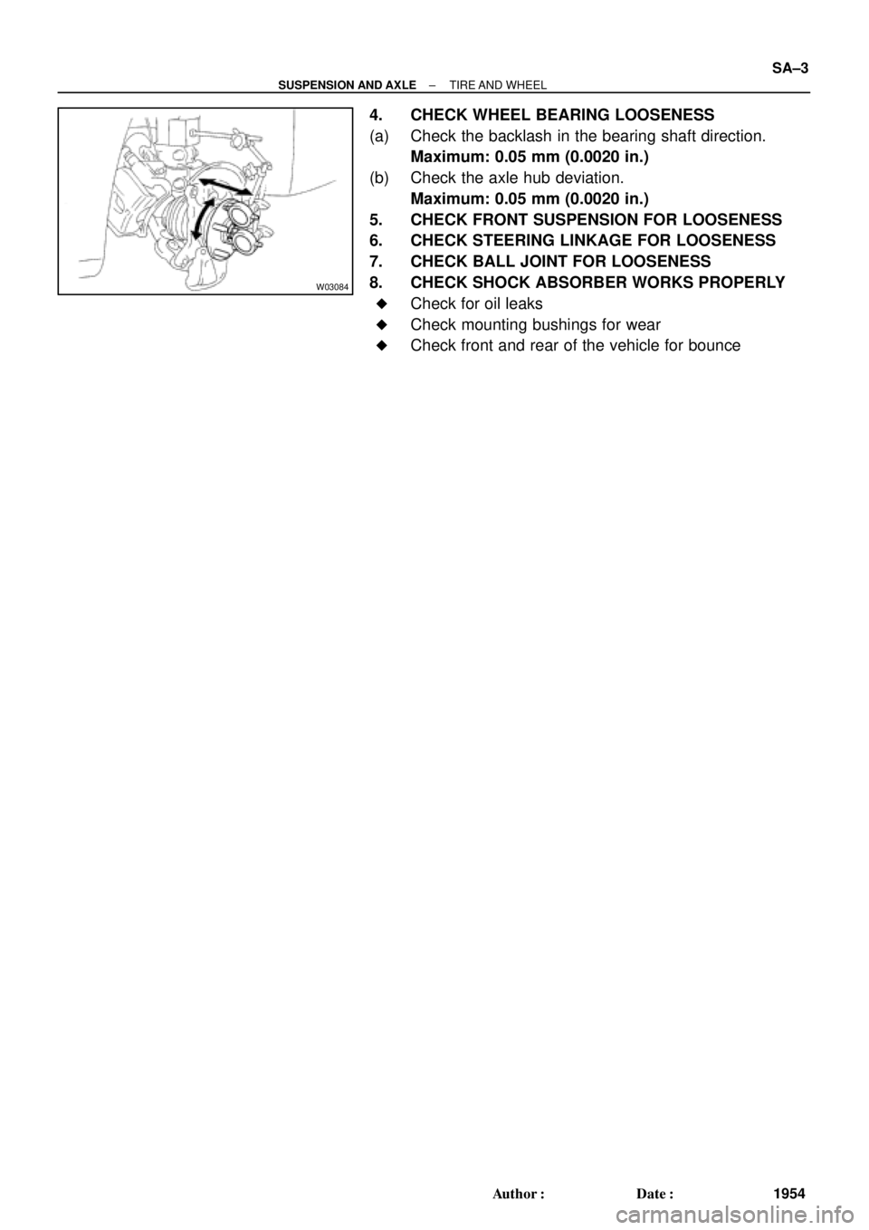
4. CHECK WHEEL BEARING LOOSENESS
(a) Check the backlash in the bearing shaft direction.
Maximum: 0.05 mm (0.0020 in.)
(b) Check the axle hub deviation.
Maximum: 0.05 mm (0.0020 in.)
5. CHECK FRONT SUSPENSION FOR LOOSENESS
6. CHECK STEERING LINKAGE FOR LOOSENESS
7. CHECK BALL JOINT FOR LOOSENESS
8. CHECK SHOCK ABSORBER WORKS PROPERLY
�Check for oil leaks
�Check mounting bushings for wear
�Check front and rear of the vehicle for bounce