Page 2437 of 4770

DI±17
252 Author�: Date�:
DTC No.
(See Page)Detection ItemTrouble AreaMIL*1Memory
P0136
(DI±77)Heated Oxygen Sensor Circuit
Malfunction
(Bank 1 Sensor 2)
�Heated oxygen")
± DIAGNOSTICSENGINE (5S±FE)
DI±17
252 Author�: Date�:
DTC No.
(See Page)Detection ItemTrouble AreaMIL*1Memory
P0136
(DI±77)Heated Oxygen Sensor Circuit
Malfunction
(Bank 1 Sensor 2)
�Heated oxygen sensor��
P0141
(DI±75) Heated Oxygen Sensor Heater
Circuit Malfunction
(Bank 1 Sensor 2)
�Same as DTC P0135��
*3
P0171
(DI±84)
System too Lean
(Fuel Trim)
(Except California Spec.)
�Air intake (hose loose)
�Fuel line pressure
�Injector blockage
�Heated oxygen sensor (bank 1 sensor 1)
�Manifold absolute pressure sensor
�Engine coolant temp. sensor
�*1�
*3
P0172
(DI±84)
System too Rich
(Fuel Trim)
(Except California Spec.)
�Fuel line pressure
�Injector leak, blockage
�Heated oxygen sensor (bank 1 sensor 1)
�Manifold absolute pressure sensor
�Engine coolant temp. sensor
�*1�
*4
P0171
(DI±79)
System too Lean
(Fuel Trim)
(Only for California Spec.)
�Air intake (hose loose)
�Fuel line pressure
�Injector blockage
�Manifold absolute pressure sensor
�Engine coolant temp. sensor
�A/F sensor
�*1�
*4
P0172
(DI±79)
System too Rich
(Fuel Trim)
(Only for California Spec.)
�Fuel line pressure
�Injector leak, blockage
�Manifold absolute pressure sensor
�Engine coolant temp. sensor
�A/F sensor
�*1�
P0300
(DI±89)Random/Multiple Cylinder
Misfire Detected
�Ignition system
�Injector
�Fuel line pressure
�EGR
Ci
P0301
P0302
P0303
P0304
(DI±89)Misfire Detected
± Cylinder 1
± Cylinder 2
± Cylinder 3
± Cylinder 4
�Compression pressure
�Valve clearance not to specification
�Valve timing
�Manifold absolute pressure sensor
�Engine coolant temp. sensor
�Open or short engine wire
�Connector connection
�ECM�
�*2�
P0325
(DI±97)Knock Sensor 1 Circuit
Malfunction�Open or short in knock sensor 1 circuit
�Knock sensor 1 (looseness)
�ECM
�*1�
P0335
(DI±100)Crankshaft Position Sensor
ºAº Circuit Malfunction
�Open or short in crankshaft position sensor circuit
�Crankshaft position sensor
�Starter
�ECM
�*1�
*1: MIL lights up
*
2: MIL lights up or blinking
*
3: Except California Specification vehicles
*
4: Only for California Specification vehicles
Page 2441 of 4770
DI1JS±03
A03431
A03430
A03537
Crankshaft
Position
SensorVSV for EGRDLC1Camshaft Position
SensorInjectorECMThrottle Position SensorManifold Absolute
Pressure Sensor
Combination Meter
(Speedometer)
DLC3
Heated Oxygen
Sensor
(Bank 1 Sensor 2)
Intake Air Temp.
Sensor
VSV for EVAP
Idle Air Control
Valve
Ignition Coil (No.1, No.2) Park/Neutral Position
Switch Engine Coolant Temp.
Sensor Heated Oxygen Sensor
(Bank 1 Sensor 1) *1 A/F Sensor *2 Knock
Sensor 1
*1: Except California Specification vehicles
*2: Only for California Specification vehicles
Vapor Pressure Sensor
Charcoal Canister
VSV for
Vapor Pressure Sensor
± DIAGNOSTICSENGINE (5S±FE)
DI±21
256 Author�: Date�:
PARTS LOCATION
Page 2442 of 4770

257 Author�: Date�:
TERMINALS OF ECM
Without engine immobiliser system
Symbols (Terminals No.)Wiring ColorConditionSTD Voltag")
DI1JT±03
D00032
E9E8E7
ECM Terminals DI±22
± DIAGNOSTICSENGINE (5S±FE)
257 Author�: Date�:
TERMINALS OF ECM
Without engine immobiliser system
Symbols (Terminals No.)Wiring ColorConditionSTD Voltage (V)
BATT (E7 ± 1) ± E1 (E9 ± 14)B ± Y e BRAlways9 ~ 14
+ B (E7 ± 12) ± E1 (E9 ± 14)B ± Y e BRIG switch ON9 ~ 14
VC (E8 ± 1) ± E2 (E8 ± 9)Ye BRIG switch ON4.5 ~ 5.5
VTA (E8 11) E2 (E8 9)LGBR
IG switch ON
Throttle valve fully closed0.3 ~ 1.0
VTA (E8 ± 11) ± E2 (E8 ± 9)LG e BRIG switch ON
Throttle valve fully open3.2 ~ 4.9
PIM (E8 2) E2 (E8 9)BYBR
IG switch ON3.3 ~ 3.9
PIM (E8 ± 2) ± E2 (E8 ± 9)B ± Y e BRApply vacuum 26.7 kPa (200 mmHg, 7.9 in.Hg)2.5 ~ 3.1
THA (E8 ± 3) ± E2 (E8 ± 9)Y ± B e BRIdling, Intake air temp. 20°C (68° F)0.5 ~ 3.4
THW (E8 ± 4) ± E2 (E8 ± 9)G ± B e BRIdling, Engine coolant temp. 80°C (176°F) 0.2 ~ 1.0
STA (E7 11) E1 (E9 14)*1 GR e BRCranking6.0 or moreSTA (E7 ± 11) ± E1 (E9 ± 14) *2 B ± O e BRCranking6.0 or more
IG switch ON9 ~ 14
#10 (E9 ± 12) ± E01 (E9 ± 13) L e BRIdlingPulse generation
(See page DI±89)
IG switch ON9 ~ 14
#20 (E9 ± 11) ± E01 (E9 ± 13)R e BRIdlingPulse generation
(See page DI±89)
IG switch ON9 ~ 14
#30 (E9 ± 25) ± E01 (E9 ± 13)Y e BRIdlingPulse generation
(See page DI±89)
IG switch ON9 ~ 14
#40 (E9 ± 24) ± E01 (E9 ± 13)W e BRIdlingPulse generation
(See page DI±89)
IGT1 (E9 ± 20) ± E1 (E9 ± 14)B e BRIdlingPulse generation
(See page DI±163)
IGT2 (E9 ± 19) ± E1 (E9 ± 14)Y ± R e BRIdlingPulse generation
(See page DI±163)
IG switch ON, Disconnect ignition coil connector4.5 ~ 5.5
IGF (E9 ± 3) ± E1 (E9 ± 14)W ± R e BRIdlingPulse generation
(See page DI±163)
*1: TMC made
*2: TMMK made
Page 2445 of 4770

A02958
E7ECM Terminals
E9E8E10
11
19
1412 10 9 8
7652
43
18 21 22
20
16151
13
17 11 14
109
87 652 4
3
21 2220
16 15 131
12 11 1 09
652
43 1 12
7 8
19
14
109 8
7652
43
18
23 2416
151
17
11 12 13 25
26
± DIAGNOSTICSENGINE (5S±FE)
DI±25
260 Author�: Date�:
With engine immobiliser system
Symbols (Terminals No.)Wiring ColorConditionSTD Voltage (V)
BATT (E7 ± 2) ± E1 (E9 ± 24)B ± Y e BRAlways9 ~ 14
+ B (E7 ± 12) ± E1 (E9 ± 24)B ± Y e BRIG switch ON9 ~ 14
VC (E8 ± 1) ± E2 (E8 ± 9)Ye BRIG switch ON4.5 ~ 5.5
VTA (E8 10) E2 (E8 9)LGBR
IG switch ON
Throttle valve fully closed0.3 ~ 1.0
VTA (E8 ± 10) ± E2 (E8 ± 9)LG e BRIG switch ON
Throttle valve fully open3.2 ~ 4.9
PIM (E8 2) E2 (E8 9)BYBR
IG switch ON3.3 ~ 3.9
PIM (E8 ± 2) ± E2 (E8 ± 9)B ± Y e BRApply vacuum 26.7 kPa (200 mmHg, 7.9 in.Hg)2.5 ~ 3.1
THA (E8 ± 3) ± E2 (E8 ± 9)Y ± B e BRIdling, Intake air temp. 20°C (68° F)0.5 ~ 3.4
THW (E8 ± 4) ± E2 (E8 ± 9)G ± B e BRIdling, Engine coolant temp. 80°C (176°F) 0.2 ~ 1.0
STA (E7 11) E1 (E9 24)*1 GR e BRCranking6.0 or moreSTA (E7 ± 11) ± E1 (E9 ± 24) *2 B ± O e BRCranking6.0 or more
#10 (E9 12)IG switch ON9 ~ 14#10 (E9 ± 12)
± E01 (E9 ± 13) L e BRIdlingPulse generation
(See page DI±89)
#20 (E9 11)IG switch ON9 ~ 14#20 (E9 ± 11)
± E01 (E9 ± 13)R e BRIdlingPulse generation
(See page DI±89)
#30 (E9 10)IG switch ON9 ~ 14#30 (E9 ± 10)
± E01 (E9 ± 13)Y e BRIdlingPulse generation
(See page DI±89)
IG switch ON9 ~ 14
#40 (E9 ± 9) ± E01 (E9 ± 13)W e BRIdlingPulse generation
(See page DI±89)
IGT1 (E9 ± 23)
± E1 (E9 ± 24)B e BRIdlingPulse generation
(See page DI±163)
IGT2 (E9 ± 22)
± E1 (E9 ± 24)Y ± R e BRIdlingPulse generation
(See page DI±163)
IG switch ON, Disconnect ignition coil connector4.5 ~ 5.5
IGF (E9 ± 17) ± E1 (E9 ± 24)W ± R e BRIdlingPulse generation
(See page DI±163)
*1: TMC made
*2: TMMK made
Page 2450 of 4770
A00309
ECM Manifold Absolute
Pressure Sensor
1PIMVC
E2 Y
B±Y
BRE8
E8
E8 3
25 V
E1 1
2
9 DI±30
± DIAGNOSTICSENGINE (5S±FE)
265 Author�: Date�:
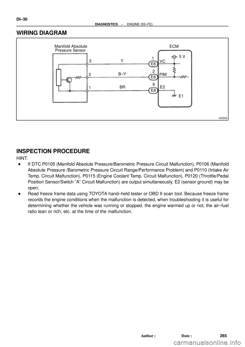
WIRING DIAGRAM
INSPECTION PROCEDURE
HINT:
�If DTC P0105 (Manifold Absolute Pressure/Barometric Pressure Circuit Malfunction), P0106 (Manifold
Absolute Pressure /Barometric Pressure Circuit Range/Performance Problem) and P0110 (Intake Air
Temp. Circuit Malfunction), P0115 (Engine Coolant Temp. Circuit Malfunction), P0120 (Throttle/Pedal
Position Sensor/Switch ºAº Circuit Malfunction) are output simultaneously, E2 (sensor ground) may be
open.
�Read freeze frame data using TOYOTA hand±held tester or OBD II scan tool. Because freeze frame
records the engine conditions when the malfunction is detected, when troubleshooting it is useful for
determining whether the vehicle was running or stopped, the engine warmed up or not, the air±fuel
ratio lean or rich, etc. at the time of the malfunction.
Page 2453 of 4770

DI±33
268 Author�: Date�:
DTC P0106 Manifold Absolute Pressure Circuit
Range/Performance Problem
CIRCUIT DESCRIPTION
Refer to DTC P0105 (Manifold Absolute Pressure/Barom")
± DIAGNOSTICSENGINE (5S±FE)
DI±33
268 Author�: Date�:
DTC P0106 Manifold Absolute Pressure Circuit
Range/Performance Problem
CIRCUIT DESCRIPTION
Refer to DTC P0105 (Manifold Absolute Pressure/Barometric Pressure Circuit Malfunction) on page
DI±29.
DTC No.DTC Detecting ConditionTrouble Area
P0106
After engine is warmed up, conditions (a) and (b) continue with
engine speed 400 ~ 1,000 rpm
(2 trip detection logic)
(a) Throttle valve fully closed
(b) Manifold absolute pressure sensor output > 3.0 V
�Manifold absolute pressure sensorP0106Condition (c) and (d) continue with engine speed 2,500 rpm or
less
(2 trip detection logic)
(c) VTA > 1.85
(d) Manifold absolute pressure sensor output < 1.0 V
�Manifold absolute ressure sensor
�Vacuum line
WIRING DIAGRAM
Refer to DTC P0105 (Manifold Absolute Pressure/Barometric Pressure Circuit Malfunction) on page
DI±29.
INSPECTION PROCEDURE
HINT:
�If DTC P0105 (Manifold Absolute Pressure/Barometric Pressure Circuit Malfunction) and P0106 (Man-
ifold Absolute Pressure /Barometric Pressure Circuit Range/Performance Problem) are output simul-
taneously, manifold absolute pressure sensor circuit may be open. Perform troubleshooting of DTC
P0105 first.
�If DTC P0105 (Manifold Absolute Pressure/Barometric Pressure Circuit Malfunction), P0106 (Manifold
Absolute Pressure /Barometric Pressure Circuit Range/Performance Problem), P0110 (Intake Air
Temp. Circuit Malfunction), P0115 (Engine Coolant Temp. Circuit Malfunction) and P0120 (Throttle/
Pedal Position Sensor/Switch ºAº Circuit Malfunction) are output simultaneously, E2 (sensor ground)
may be open.
�Read freeze frame data using TOYOTA hand±held tester or OBD II scan tool. Because freeze frame
records the engine conditions when the malfunction is detected, when troubleshooting it is useful for
determining whether the vehicle was running or stopped, the engine warmed up or not, the air±fuel
ratio lean or rich, etc. at the time of the malfunction.
1 Are there any other codes (besides DTC P0106) being output?
YES Go to relevant DTC chart.
NO
DI00N±04
Page 2456 of 4770
A00310
Intake Air Temp. Sensor
E8
E83
9ECM
5 V
THA
E2
E1 R
Y±B
BR 2
1 DI±36
± DIAGNOSTICSENGINE (5S±FE)
271 Author�: Date�:
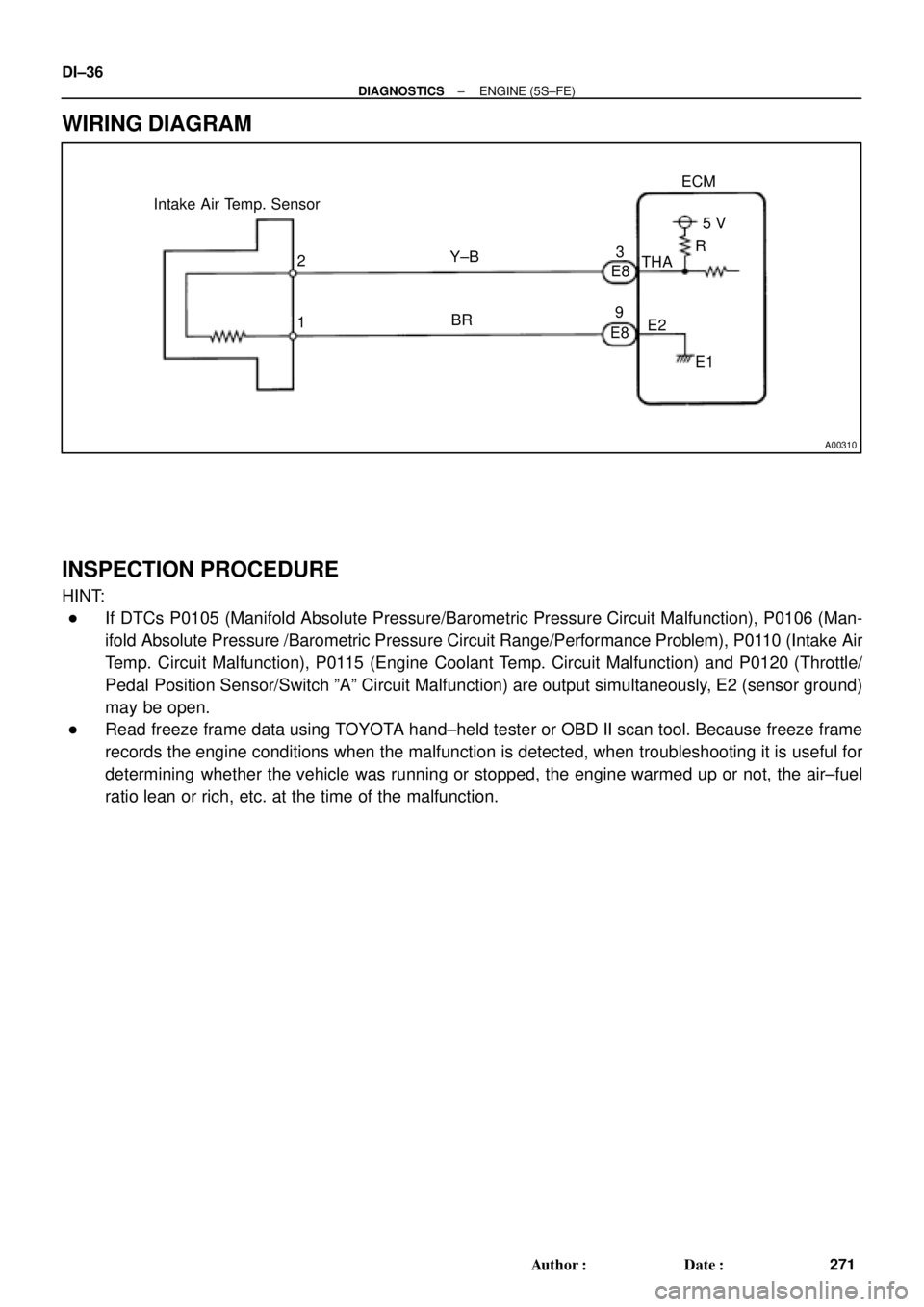
WIRING DIAGRAM
INSPECTION PROCEDURE
HINT:
�If DTCs P0105 (Manifold Absolute Pressure/Barometric Pressure Circuit Malfunction), P0106 (Man-
ifold Absolute Pressure /Barometric Pressure Circuit Range/Performance Problem), P0110 (Intake Air
Temp. Circuit Malfunction), P0115 (Engine Coolant Temp. Circuit Malfunction) and P0120 (Throttle/
Pedal Position Sensor/Switch ºAº Circuit Malfunction) are output simultaneously, E2 (sensor ground)
may be open.
�Read freeze frame data using TOYOTA hand±held tester or OBD II scan tool. Because freeze frame
records the engine conditions when the malfunction is detected, when troubleshooting it is useful for
determining whether the vehicle was running or stopped, the engine warmed up or not, the air±fuel
ratio lean or rich, etc. at the time of the malfunction.
Page 2461 of 4770
± DIAGNOSTICSENGINE (5S±FE)
DI±41
276 Author�: Date�:
DTC P0115 Engine Coolant Temp. Circuit Malfunction
CIRCUIT DESCRIPTION
A thermistor built into the engine coolant temp. sensor changes the resistance value according to the engine
coolant temp.
The structure of the sensor and connection to the ECM is the same as in the intake air temp. circuit malfunc-
tion shown on page DI±35.
If the ECM detects the DTC P0115, it operates fail safe function in which the engine coolant temperature
is assumed to be 80°C (176°F).
DTC No.Detection ItemTrouble Area
P0115Open or short in engine coolant temp. sensor circuit
�Open or short in engine coolant temp. sensor circuit
�Engine coolant temp. sensor
�ECM
HINT:
After confirming DTC P0115, use the OBD II scan tool or TOYOTA hand±held tester to confirm the engine
coolant temp. from the CURRENT DATA.
Temp. DisplayedMalfunction
±40°C (±40°F)Open circuit
140°C (284°F) or moreShort circuit
DI00P±05

DL")