Page 407 of 4770
DIAGNOSTIC CHART
HINT If diagnostic trouble codes ª22º (engine coolant temperature sensor circuit), ª24º (intake air temperature sensor cir-
cuit), ª31º (manifold absolute pressure sensor circuit) and ª41º (throttle position sensor circuit) are output simultaneously, E2
(sensor ground) may be open, OK Check for momentary interruption
Check for open and short in harness and connector
between ECM and engine coolant temp. sensor.Check for momentary interruption
(See page EG1±309).
Repair or replace harness or
connector.Replace engine coolant temp. sensor.
WIRING DIAGRAM
Check resistance of sensor.
Check and replace ECM.Check voltage of sensor.
± 5S±FE ENGINECIRCUIT INSPECTIONEG1±357
Page 410 of 4770

DIAGNOSTIC CHART
HINT: If diagnostic trouble codes ª22º (engine coolant temperature sensor circuit), ª24º (intake air
temperature sensor circuit), ª31º (manifold absolute pressure sensor circuit) and ª41º (throt±
tle position sensor circuit) are output simultaneously, E2 (sensor ground) may be open.
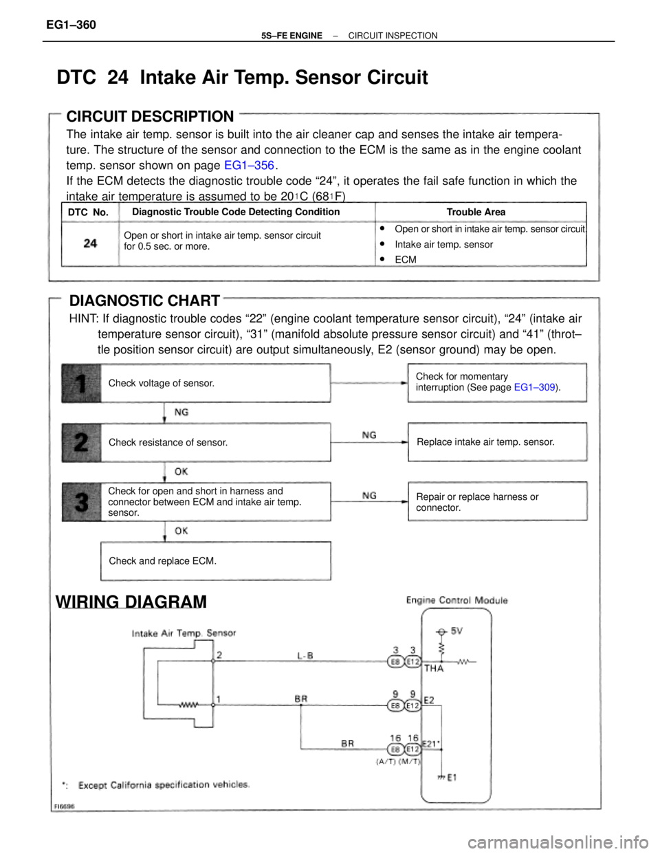
CIRCUIT DESCRIPTION
The intake air temp. sensor is built into the air cleaner cap and senses the intake air tempera-
ture. The structure of the sensor and connection to the ECM is the same as in the engine coolant
temp. sensor shown on page EG1±356.
If the ECM detects the diagnostic trouble code ª24º, it operates the fail safe function in which the
intake air temperature is assumed to be 20
�C (68�F)
w
Open or short in intake air temp. sensor circuit.
wIntake air temp. sensor
wECM
Check for open and short in harness and
connector between ECM and intake air temp.
sensor.Open or short in intake air temp. sensor circuit
for 0.5 sec. or more.
Check for momentary
interruption (See page EG1±309). Diagnostic Trouble Code Detecting Condition
Repair or replace harness or
connector.Replace intake air temp. sensor.
WIRING DIAGRAM
Check resistance of sensor.
Check and replace ECM. Check voltage of sensor.Trouble Area
DTC 24 Intake Air Temp. Sensor Circuit
DTC No.
± 5S±FE ENGINECIRCUIT INSPECTIONEG1±360
Page 415 of 4770
WIRING DIAGRAM
Refer to page EG1±354 for the WIRING DIAGRAM.
Does malfunction disappear when a good main
oxygen sensor is installed?Check each item found to be a possible cause
of problem.
Does malfunction disappear when a good main
oxygen sensor is installed?Check each item found to be a possible cause
of problem.Check for open and short in harness and
connector.Repair or replace harness or
connector.
DIAGNOSTIC CHART
Check voltage of terminal OX1.Check voltage of terminal VF1.
Replace main oxygen sensor.
Replace main oxygen sensor. Check and replace ECM.
Check and replace ECM.Check compression.
Check compression.Repair or replace.
Repair or replace.Repair or replace.
Repair or replace.N G TypeII
NG Type I
YESYES
± 5S±FE ENGINECIRCUIT INSPECTIONEG1±365
Page 421 of 4770
Are there any other codes (beside Code 27)
being output?Go to relevant diagnostic trouble
code chart.
DIAGNOSTIC CHART
WIRING DIAGRAM
Replace sub oxygen sensor.YES
± 5S±FE ENGINECIRCUIT INSPECTIONEG1±371
Page 423 of 4770
Check for open and short in harness and
connector between manifold absolute pressure
sensor and ECM.
Check and replace manifold absolute pressure
sensor.When diagnostic trouble code 31 is
displayed, check and replace ECM.
Repair or replace harness or
connector.
DIAGNOSTIC CHART
Check voltage of terminal PIM.Check voltage of terminal VC. Check and replace ECM.
DIA RAMWIRING DIAGRAM
± 5S±FE ENGINECIRCUIT INSPECTIONEG1±373
Page 427 of 4770
DIAGNOSTIC CHART
HINT: If diagnostic trouble codes ª22º (engine coolant temperature sensor circuit), ª24º (intake air
temperature sensor circuit),ª31º (manifold absolute pressure sensor circuit) and ª41º (throttle posi±
tion sensor circuit) are output simultaneously, E2 (sensor ground) may be open.
Check for open and short in harness and
connector between throttle position sensor and
ECM.Check for momentary interruption
(See page EG1±309).
Adjust or replace throttle position
sensor.
Repair or replace harness or
connector. Check operation for throttle position sensor.Check voltage of throttle position sensor.
WIRING DIAGRAM
Check and replace ECM.
± 5S±FE ENGINECIRCUIT INSPECTIONEG1±377
Page 431 of 4770
Check speedometer circuit.
(See page BE±66). Check speedometer circuit.
(See page BE±66).
DIAGNOSTIC CHART
Check operation of speedometer.
WIRING DIAGRAM
Check voltage of terminal SPD.
Check and replace ECM.
± 5S±FE ENGINECIRCUIT INSPECTIONEG1±381
Page 433 of 4770

CIRCUIT DESCRIPTION
When the engine is cranked, the intake air flow is slow, so fuel vaporization is poor. A rich mixture
is therefore necessary in order to achieve good startability. While the engine is being cranked, the
battery positive voltage is applied to terminal STA of the ECM. The starter signal is mainly used to
increase the fuel injection volume for the starting injection control and after±start injection control.
DIAGNOSTIC CHART
HINT: This diagnostic chart is based on the premise that the engine is cranked normally. If the
engine is not cranked, proceed to the matrix chart of problem symptoms on page EG1±327, w
Open or short in starter signal circuit.
wOpen or short in ignition switch or starter
relay circuit.
wECM
Check for open in harness and connector
between ECM and relay.Proceed to next circuit inspection
shown on matrix chart (See page
E±G±327). Diagnostic Trouble Code Detecting Condition
Repair or replace harness or
connector.
WIRING DIAGRAM
No starter signal to ECM.
Check and replace ECM.Check for the test mode.Trouble Area
DTC 43 Starter Signal Circuit
DTC No.
± 5S±FE ENGINECIRCUIT INSPECTIONEG1±383