Page 69 of 4770
4. FURTHER CHECK IGNITION TIMING
Ignition timing:
0 ± 10� BTDC @ idle
(Transmission in neutral position)
HINT: The timing mark moves in a range between 0�
and 10�. (c) Loosen the bolt (California) or 2 bolts (except Califor±
nia), and adjust by turning the distributor.
(d) Tighten the bolt (California) or 2 bolts (except Califor±
nia), and recheck the ignition timing.
Torque: 19 N±m (195 kgf±cm, 14 ft±lbf)
5. DISCONNECT TACHOMETER AND TIMING LIGHT
FROM ENGINE(e) Remove the SST.
SST 09843±18020
± 5S±FE ENGINEENGINE MECHANICALEG1±19
Page 70 of 4770

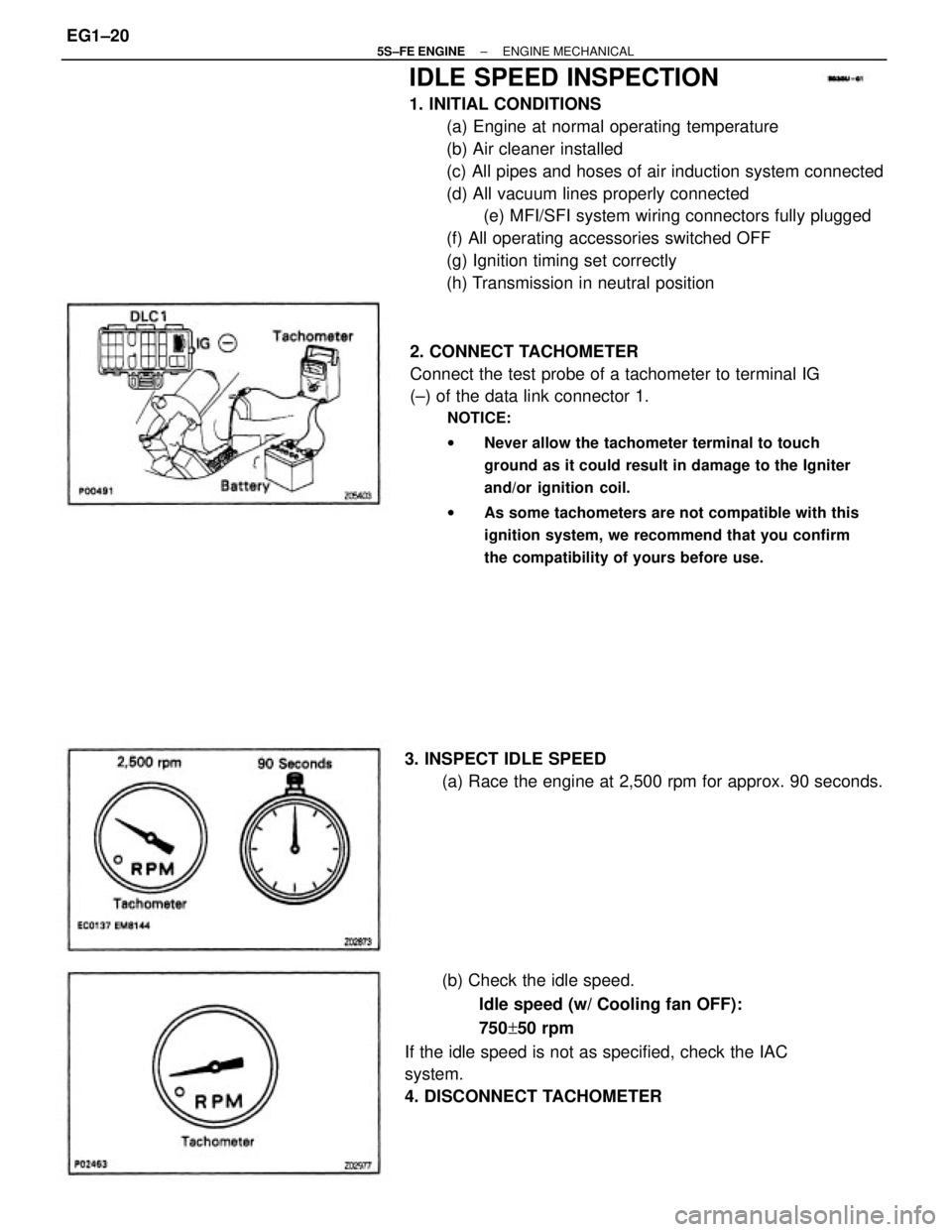
IDLE SPEED INSPECTION
1. INITIAL CONDITIONS
(a) Engine at normal operating temperature
(b) Air cleaner installed
(c) All pipes and hoses of air induction system connected
(d) All vacuum lines properly connected
(e) MFI/SFI system wiring connectors fully plugged
(f) All operating accessories switched OFF
(g) Ignition timing set correctly
(h) Transmission in neutral position
2. CONNECT TACHOMETER
Connect the test probe of a tachometer to terminal IG
(±) of the data link connector 1.
NOTICE:
wNever allow the tachometer terminal to touch
ground as it could result in damage to the Igniter
and/or ignition coil.
wAs some tachometers are not compatible with this
ignition system, we recommend that you confirm
the compatibility of yours before use.
(b) Check the idle speed.
Idle speed (w/ Cooling fan OFF):
750+50 rpm
If the idle speed is not as specified, check the IAC
system.
4. DISCONNECT TACHOMETER 3. INSPECT IDLE SPEED
(a) Race the engine at 2,500 rpm for approx. 90 seconds.
± 5S±FE ENGINEENGINE MECHANICALEG1±20
Page 71 of 4770

IDLE AND OR 2,500 RPM CO/HC
CHECK
HINT: This check is used only to determine whether or
not the idle CO/HC complies with regulations.
1. INITIAL CONDITIONS
(a) Engine at normal operating temperature
(b) Air cleaner installed
(c) All pipes and hoses of air induction system connected
(d) All accessories switched OFF
(e) All vacuum lines properly connected
HINT: All vacuum hoses for EGR systems, etc. should
be properly connected.
(f) MFI/SFI system wiring connectors fully plugged
(g) Ignition timing set correctly
(h) Transmission in neutral position
(i) Tachometer and CO/HC meter calibrated by hand.
4. INSERT CO/HC METER TESTING PROBE AT LEAST
40 cm (1.3 ft) INTO TAILPIPE DURING IDLING
5. IMMEDIATTELY CHECK CO/HC CONCENTRATION
AT IDLE AND/OR 2,500 RPM
Complete the measuring within 3 minutes.
HINT: When performing the 2 mode (2,500 rpm and
idle) test, follow the measurement order prescribed by
the applicable local regulations. 2. START ENGINE
3. RACE ENGINE AT 2,500 RPM FOR APPROX. 180
SECONDS
± 5S±FE ENGINEENGINE MECHANICALEG1±21
Page 239 of 4770
2. INSPECT INJECTOR RESISTANCE
(a) Disconnect the injector connector.
(b) Using an ohmmeter, measure the resistance between
the terminals.
Resistance:
Approx. 13.8�
If the resistance is not as specified, replace the injector.
(c) Reconnect the injector connector.
ON±VEHICLE INSPECTION
1. INSPECT INJECTOR OPERATION
Check operation sound from each injector.
(a) With the engine running or cranking, use a sound
scope to check that there is normal operating noise in
proportion to engine speed.
(b) If you have no sound scope, you can check the injec±
tor transmission operation with your finger.
If no sound or unusual sound is heard, check the
wiring connector, injector or injection signal from the
ECM.
INJECTOR
± 5S±FE ENGINEMFI/SFI SYSTEMEG1±189
Page 262 of 4770
(b) Using SST, connect terminals TE1 and E1 of the data
link connector 1.
SST 09843±18020
(c) Maintain engine speed in the range between 900 ±
1,300 rpm for 5 seconds. Check that it returns to idle
speed.
If the engine speed operation is not as specified,
check the IAC valve, wiring and ECM.
ON±VEHICLE INSPECTION
1. INSPECT IAC VALVE OPERATION
(a) Initial conditions:
wEngine at normal operating temperature
wIdle speed set correctly
wTransmission in neutral position
IDLE AIR CONTROL (IAC) VALVE
(d) Remove the SST.
SST 09843±18020
± 5S±FE ENGINEMFI/SFI SYSTEMEG1±212
Page 289 of 4770

RADIATOR
The radiator performs the function of cooling the coolant which has passed through the water
jacket and become hot, and it is mounted in the front of the vehicle. The radiator consists of an
upper tank and lower tank, and a core which connects the two tanks. The upper tank contains the
inlet for coolant from the water jacket and the filler inlet. It also has a hose attached through
which excess coolant or steam can flow. The lower tank has an outlet and drain cock for the
coolant. The core contains many tubes through which coolant flows from the upper tank to the
lower tank as well as to cooling fins which radiate heat away from the coolant in the tubes. The
air sucked through the radiator by the electric fan, as well as the wind generated by the vehicle's
travel, passes through the radiator, cooling the coolant. Models with automatic transmission
include an automatic transmission fluid cooler built into the lower tank of the radiator. A fan with
an electric motor is mounted behind the radiator to assist the flow of air through the radiator. The
fan operates when the engine coolant temperature becomes high in order to prevent it from be-
coming too high.
RADIATOR CAP
The radiator cap is a pressure type cap which seals the radiator, resulting in pressurization of the
radiator as the coolant expands. The pressurization prevents the coolant from boiling even when
the engine coolant temperature exceeds 100°C (212°F). A relief valve (pressurization valve) and a
vacuum valve (negative pressure valve) are built into the radiator cap. The relief valve opens and
lets steam escape through the overflow pipe when the pressure generated inside the cooling sys-
tem exceeds the limit (coolant temperature: 110±120°C (230±248°F), pressure; 58.8103.0 kpa
(0.6±1.05 kgf/cm
2, 8.5±14.9 psi). The vacuum valve opens to alleviate the vacuum which develops
in the cooling system after the engine is stopped and the engine coolant temperature drops. The
valve's opening allows the coolant in the reservoir tank to return to the cooling system.
RESERVOIR TANK
The reservoir tank is used to catch coolant which overflows from the cooling system as a result
of volumetric expansion when the coolant is heated. The coolant in the reservoir tank returns to
the radiator when the coolant temperature drops, thus keeping the radiator full at all times and
avoiding needless coolant loss.
Check the reservoir tank level to learn if the coolant needs to be replenished.
WATER PUMP
The water pump is used for forced circulation of coolant through the cooling system. It is
mounted on the front of the cylinder block and driven by a timing belt.
THERMOSTAT
The thermostat has a wax type bypass valve and is mounted in the water inlet housing. The
thermostat includes a type of automatic valve operated by fluctuations in the engine coolant
temperature. This valve closes when the engine coolant temperature drops, preventing the
circulation of coolant through the engine and thus permitting the engine to warm up rapidly. The
valve opens when the engine coolant temperature has risen, allowing the circulation of coolant.
Wax inside the thermostat expands when heated and contracts when cooled. Heating the wax
thus generates pressure which overpowers the force of the spring which keeps the valve closed,
thus opening the valve. When the wax cools, its contraction allows the force of the spring to take
effect once more, closing the valve. The thermostat in this engine operates at a temperature of
82�C (180�F).
± 5S±FE ENGINECOOLING SYSTEMEG1±239
Page 310 of 4770
10. CONNECT ELECTRIC COOLING FAN CONNECTORS
11. CONNECT ENGINE COOLANT TEMPERATURE
SWITCH CONNECTOR TO FAN SHROUD
12. w/ CRUISE CONTROL SYSTEM:
INSTALL CRUISE CONTROL ACTUATOR COVER
13. FILL WITH ENGINE COOLANT
(See page EG1±241)
14. CONNECT NEGATIVE (±) TERMINAL CABLE TO
BATTERY
15. START ENGINE AND CHECK FOR LEAKS
16. A/T:
CHECK AUTOMATIC TRANSMISSION (A/T) FLUID
LEVEL
NOTICE: Do not overfill.
± 5S±FE ENGINECOOLING SYSTEMEG1±260
Page 348 of 4770

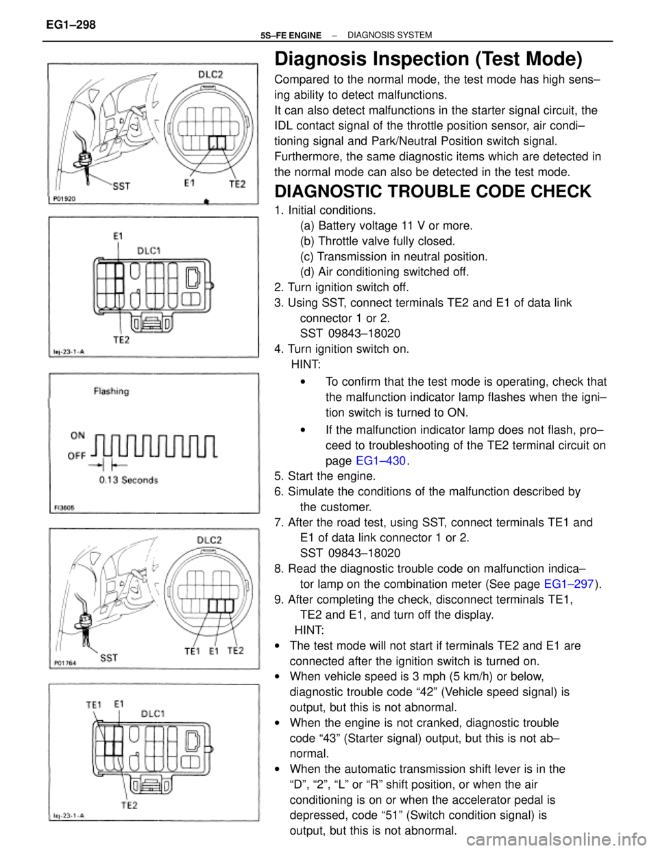
Diagnosis Inspection (Test Mode)
Compared to the normal mode, the test mode has high sens±
ing ability to detect malfunctions.
It can also detect malfunctions in the starter signal circuit, the
IDL contact signal of the throttle position sensor, air condi±
tioning signal and Park/Neutral Position switch signal.
Furthermore, the same diagnostic items which are detected in
the normal mode can also be detected in the test mode.
DIAGNOSTIC TROUBLE CODE CHECK
1. Initial conditions.
(a) Battery voltage 11 V or more.
(b) Throttle valve fully closed.
(c) Transmission in neutral position.
(d) Air conditioning switched off.
2. Turn ignition switch off.
3. Using SST, connect terminals TE2 and E1 of data link
connector 1 or 2.
SST 09843±18020
4. Turn ignition switch on.
HINT:
wTo confirm that the test mode is operating, check that
the malfunction indicator lamp flashes when the igni±
tion switch is turned to ON.
wIf the malfunction indicator lamp does not flash, pro±
ceed to troubleshooting of the TE2 terminal circuit on
page EG1±430.
5. Start the engine.
6. Simulate the conditions of the malfunction described by
the customer.
7. After the road test, using SST, connect terminals TE1 and
E1 of data link connector 1 or 2.
SST 09843±18020
8. Read the diagnostic trouble code on malfunction indica±
tor lamp on the combination meter (See page EG1±297).
9. After completing the check, disconnect terminals TE1,
TE2 and E1, and turn off the display.
HINT:
wThe test mode will not start if terminals TE2 and E1 are
connected after the ignition switch is turned on.
wWhen vehicle speed is 3 mph (5 km/h) or below,
diagnostic trouble code ª42º (Vehicle speed signal) is
output, but this is not abnormal.
wWhen the engine is not cranked, diagnostic trouble
code ª43º (Starter signal) output, but this is not ab±
normal.
wWhen the automatic transmission shift lever is in the
ªDº, ª2º, ªLº or ªRº shift position, or when the air
conditioning is on or when the accelerator pedal is
depressed, code ª51º (Switch condition signal) is
output, but this is not abnormal.
± 5S±FE ENGINE DIAGNOSIS SYSTEMEG1±298