Page 183 of 4770

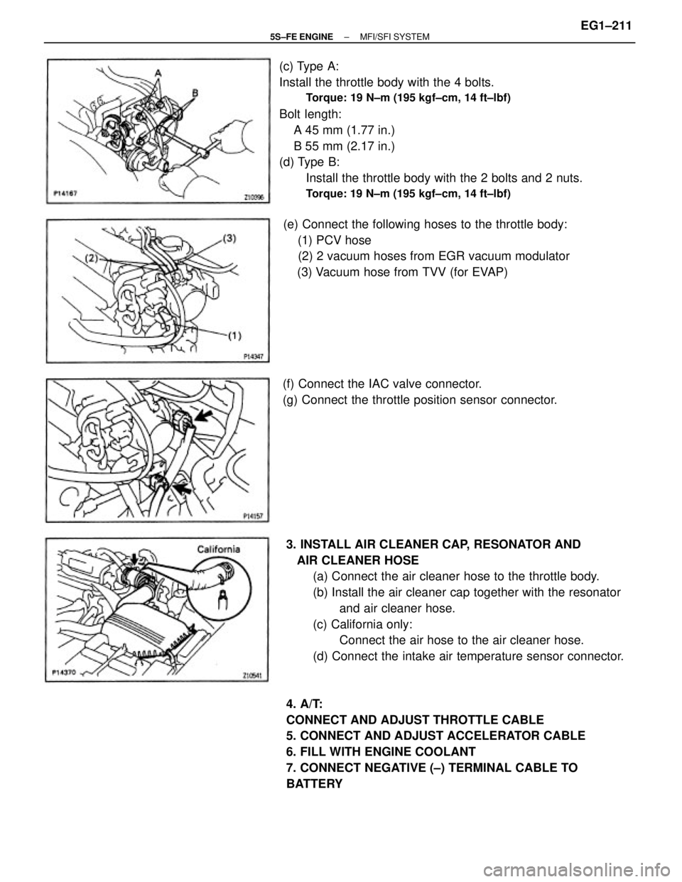
27. INSTALL AIR CLEANER ASSEMBLY, RESONATOR
AND AIR CLEANER HOSE
(a) Install the air cleaner case with 3 bolts.
(b) Install the element.
(c) Connect the air cleaner hose to the throttle body.
(d) Install the air cleaner cap together with the resonator
and air cleaner hose.
(e) California only:
Connect the air hose to the air cleaner hose.
(f) Connect the intake air temperature sensor connector.
28. A/T:
CONNECT AND ADJUST THROTTLE CABLE
29. CONNECT AND ADJUST ACCELERATOR CABLE
30. FILL WITH ENGINE COOLANT
31. FILL WITH ENGINE OIL
32. CONNECT NEGATIVE (±) TERMINAL CABLE TO
BATTERY
33. START ENGINE AND CHECK FOR LEAKS
34. PREFORM ENGINE ADJUSTMENT
35. INSTALL ENGINE UNDER COVERS
36. INSTALL HOOD
37. PERFORM ROAD TEST
Check for abnormal noises, shock, slippage, correct
shift points and smooth operation.
38. RECHECK ENGINE COOLANT AND ENGINE OIL
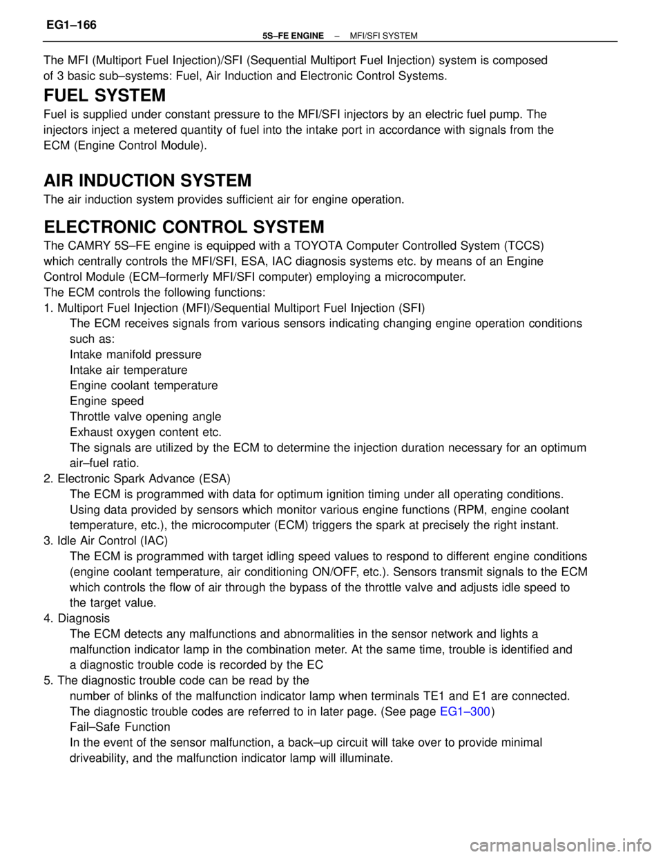
LEVELS26. w/ CRUISE CONTROL SYSTEM:
INSTALL CRUISE CONTROL ACTUATOR
(a) Install the actuator and bracket with the 3 bolts.
(b) Connect the actuator connector.
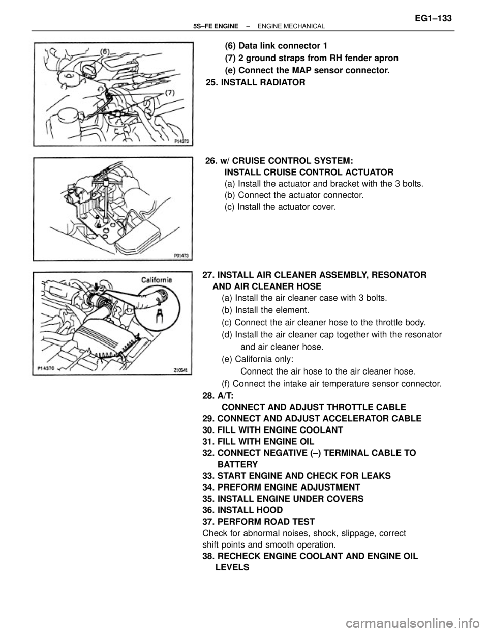
(c) Install the actuator cover.(6) Data link connector 1
(7) 2 ground straps from RH fender apron
(e) Connect the MAP sensor connector.
25. INSTALL RADIATOR
± 5S±FE ENGINEENGINE MECHANICALEG1±133
Page 203 of 4770
EGR SYSTEM INSPECTION
1. CHECK AND CLEAN FILTER IN EGR VACUUM
MODULATOR
(a) Check the filter for contamination or damage.
(b) Using compressed air, clean the filter.
HINT: Install the filter with the coarser surface facing
the atmospheric side (outward).
2. PREPARATION
Using a 3±way connector, connect a vacuum gauge
to the hose between the EGR valve and VSV.
3. CHECK SEATING OF EGR VALVE
Start the engine and check that the engine starts and
runs at idle.
6. CHECK VSV AND EGR VACUUM MODULATOR
WITH HOT ENGINE
(a) Warm up the engine.
(b) Check that the vacuum gauge indicates low vacuum
at 2,500 rpm. 5. CHECK VSV
(a) The engine coolant temperature should be below
60�C (140�F) (A/T) or 55�C (131 �F) (M/T).
(b) Check that the vacuum gauge indicates zero at 2.500
rpm. 4. CONNECT TERMINALS TE1 AND E1
Using SST, connect terminals TE 1 and E 1 of the data
link connector 1.
SST 09843±18020
± 5S±FE ENGINEEMISSION CONTROL SYSTEMSEG1±153
Page 216 of 4770

ELECTRONIC CONTROL SYSTEM
The CAMRY 5S±FE engine is equipped with a TOYOTA Computer Controlled System (TCCS)
which centrally controls the MFI/SFI, ESA, IAC diagnosis systems etc. by means of an Engine
Control Module (ECM±formerly MFI/SFI computer) employing a microcomputer.
The ECM controls the following functions:
1. Multiport Fuel Injection (MFI)/Sequential Multiport Fuel Injection (SFI)
The ECM receives signals from various sensors indicating changing engine operation conditions
such as:
Intake manifold pressure
Intake air temperature
Engine coolant temperature
Engine speed
Throttle valve opening angle
Exhaust oxygen content etc.
The signals are utilized by the ECM to determine the injection duration necessary for an optimum
air±fuel ratio.
2. Electronic Spark Advance (ESA)
The ECM is programmed with data for optimum ignition timing under all operating conditions.
Using data provided by sensors which monitor various engine functions (RPM, engine coolant
temperature, etc.), the microcomputer (ECM) triggers the spark at precisely the right instant.
3. Idle Air Control (IAC)
The ECM is programmed with target idling speed values to respond to different engine conditions
(engine coolant temperature, air conditioning ON/OFF, etc.). Sensors transmit signals to the ECM
which controls the flow of air through the bypass of the throttle valve and adjusts idle speed to
the target value.
4. Diagnosis
The ECM detects any malfunctions and abnormalities in the sensor network and lights a
malfunction indicator lamp in the combination meter. At the same time, trouble is identified and
a diagnostic trouble code is recorded by the EC
5. The diagnostic trouble code can be read by the
number of blinks of the malfunction indicator lamp when terminals TE1 and E1 are connected.
The diagnostic trouble codes are referred to in later page. (See page EG1±300)
Fail±Safe Function
In the event of the sensor malfunction, a back±up circuit will take over to provide minimal
driveability, and the malfunction indicator lamp will illuminate. The MFI (Multiport Fuel Injection)/SFI (Sequential Multiport Fuel Injection) system is composed
of 3 basic sub±systems: Fuel, Air Induction and Electronic Control Systems.
FUEL SYSTEM
Fuel is supplied under constant pressure to the MFI/SFI injectors by an electric fuel pump. The
injectors inject a metered quantity of fuel into the intake port in accordance with signals from the
ECM (Engine Control Module).
AIR INDUCTION SYSTEM
The air induction system provides sufficient air for engine operation.
± 5S±FE ENGINEMFI/SFI SYSTEMEG1±166
Page 219 of 4770
The control system consists of sensors which detect various engine conditions, and a ECM which
determines the injection volume (timing) based on the signals from the sensors.
The various sensors detect the intake air pressure, engine speed, oxygen density in the exhaust
gas, engine coolant temperature, intake air temperature and atmospheric pressure etc. and
convert the information into an electrical signal which. is sent to the ECM. Based on these signals,
the ECM calculates the optimum ignition timing for the current conditions and operates the
injectors.
The ECM not only controls the fuel injection timing, but also the self diagnostic function which
records the occurrence of a malfunction, ignition timing control, idle speed control and EGR
control.
ELECTRONIC CONTROL SYSTEM
± 5S±FE ENGINEMFI/SFI SYSTEMEG1±169
Page 241 of 4770

5. REMOVE AIR CLEANER CAP, RESONATOR AND
AIR CLEANER HOSE
(a) Disconnect the intake air temperature sensor connector.
(b) California only:
Disconnect the air hose from the air cleaner hose.
(c) Loosen the air cleaner hose clamp bolt.
(d) Disconnect the 4 air cleaner cap clips.
(e) Disconnect the air cleaner hose from the throttle
body, and remove the air cleaner cap together with
the resonator and air cleaner hose.
INJECTORS REMOVAL
(See Components for Removal and Installation)
1. DISCONNECT NEGATIVE (±) TERMINAL CABLE
FROM BATTERY
CAUTION: Work must be started after 90 seconds from
the time the ignition switch i: turned to the ªLOCKº
position and the negative (±) terminal cable is discon±
nected from the battery.
2. DRAIN ENGINE COOLANT
3. A/T:
DISCONNECT THROTTLE CABLE FROM
THROTTLE BODY
4. DISCONNECT ACCELERATOR CABLE FROM
THROTTLE BODY
6. REMOVE THROTTLE BODY
(a) Disconnect throttle position sensor connector.
(b) Disconnect IAC valve connector.
± 5S±FE ENGINEMFI/SFI SYSTEMEG1±191
Page 251 of 4770

(c) Type A:
Install the throttle body with the 4 bolts.
Torque: 19 N±m (195 kgf±cm, 14 ft±lbf)
Bolt length:
A 45 mm (1.77 in.)
B 55 mm (2.17 in.)
(d) Type B:
Install the throttle body with the 2 bolts and 2 nuts.
Torque: 19 N±m (195 kgf±cm, 14 ft±lbf)
14. INSTALL AIR CLEANER CAP, RESONATOR AND
AIR CLEANER HOSE
(a) Connect the air cleaner hose to the throttle body.
(b) Install the air cleaner cap together with the resonator
and air cleaner hose.
(c) California only:
Connect the air hose to the air cleaner hose.
(d) Connect the intake air temperature sensor connector.
15. A/T:
CONNECT AND ADJUST THROTTLE CABLE
16. CONNECT AND ADJUST ACCELERATOR CABLE
17. FILL WITH ENGINE COOLANT
Capacity:
6.3 liters (6.7 US qts. 5.5 Imp. qts)
18. CONNECT NEGATIVE (±) TERMINAL CABLE TO
BATTERY (e) Connect the following hoses to the throttle body:
(1) PCV hose
(2) 2 vacuum hoses from EGR vacuum modulator
(3) Vacuum hose from TVV (for EVAP)
(f) Connect the IAC valve connector.
(g) Connect the throttle position sensor connector.
± 5S±FE ENGINEMFI/SFI SYSTEMEG1±201
Page 257 of 4770
5. REMOVE AIR CLEANER CAP, RESONATOR AND
AIR CLEANER HOSE
(a) Disconnect the intake air temperature sensor connec±
tor.
(b) California only:
Disconnect the air hose from the air cleaner hose.
(c) Loosen the air cleaner hose clamp bolt.
(d) Disconnect the 4 air cleaner cap clips.
(e) Disconnect the air cleaner hose from the throttle
body, and remove the air cleaner cap together with
the resonator and air cleaner hose. 1. DISCONNECT NEGATIVE (±) TERMINAL CABLE
FROM BATTERY
CAUTION: Work must be started after 90 seconds from
the time the ignition switch is turned to the ªLOCKº
position and the negative (±) terminal cable is discon±
nected from the battery.
2. DRAIN ENGINE COOLANT
3. DISCONNECT ACCELERATOR CABLE FROM
THROTTLE LINKAGE
4. A/T:
DISCONNECT THROTTLE CABLE FROM
THROTTLE LINKAGE
6. REMOVE THROTTLE BODY
(a) Disconnect the throttle position sensor connector.
(b) Disconnect the IAC valve connector.
THROTTLE BODY REMOVAL
± 5S±FE ENGINEMFI/SFI SYSTEMEG1±207
Page 261 of 4770

(c) Type A:
Install the throttle body with the 4 bolts.
Torque: 19 N±m (195 kgf±cm, 14 ft±lbf)
Bolt length:
A 45 mm (1.77 in.)
B 55 mm (2.17 in.)
(d) Type B:
Install the throttle body with the 2 bolts and 2 nuts.
Torque: 19 N±m (195 kgf±cm, 14 ft±lbf)
3. INSTALL AIR CLEANER CAP, RESONATOR AND
AIR CLEANER HOSE
(a) Connect the air cleaner hose to the throttle body.
(b) Install the air cleaner cap together with the resonator
and air cleaner hose.
(c) California only:
Connect the air hose to the air cleaner hose.
(d) Connect the intake air temperature sensor connector.
4. A/T:
CONNECT AND ADJUST THROTTLE CABLE
5. CONNECT AND ADJUST ACCELERATOR CABLE
6. FILL WITH ENGINE COOLANT
7. CONNECT NEGATIVE (±) TERMINAL CABLE TO
BATTERY (e) Connect the following hoses to the throttle body:
(1) PCV hose
(2) 2 vacuum hoses from EGR vacuum modulator
(3) Vacuum hose from TVV (for EVAP)
(f) Connect the IAC valve connector.
(g) Connect the throttle position sensor connector.
± 5S±FE ENGINEMFI/SFI SYSTEMEG1±211