Page 357 of 4770
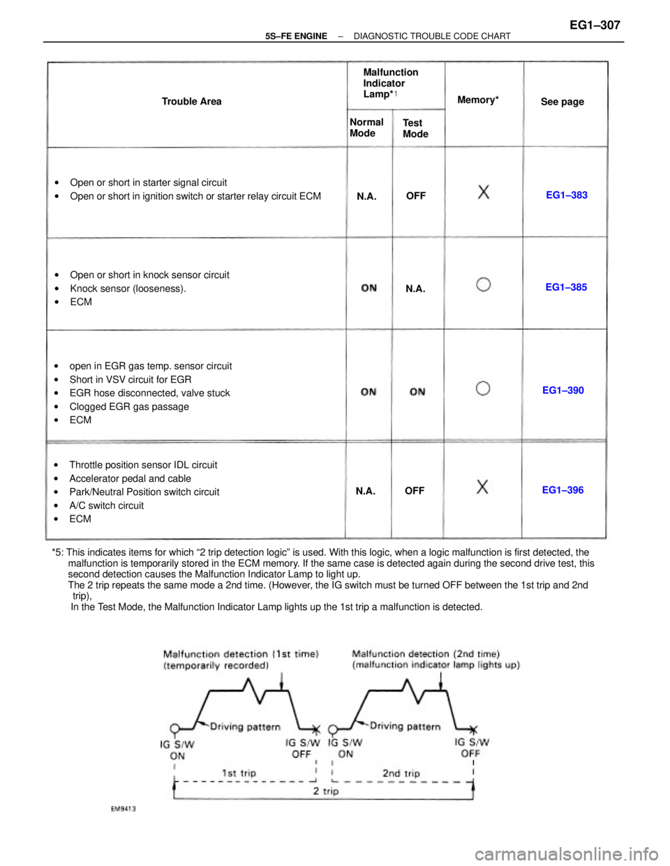
*5: This indicates items for which ª2 trip detection logicº is used. With this logic, when a logic malfunction is first detected, the
malfunction is temporarily stored in the ECM memory. If the same case is detected again during the second drive test, this
second detection causes the Malfunction Indicator Lamp to light up.
The 2 trip repeats the same mode a 2nd time. (However, the IG switch must be turned OFF between the 1st trip and 2nd
trip),
In the Test Mode, the Malfunction Indicator Lamp lights up the 1st trip a malfunction is detected.wopen in EGR gas temp. sensor circuit
wShort in VSV circuit for EGR
wEGR hose disconnected, valve stuck
wClogged EGR gas passage
wECM
wThrottle position sensor IDL circuit
wAccelerator pedal and cable
wPark/Neutral Position switch circuit
wA/C switch circuit
wECM wOpen or short in starter signal circuit
wOpen or short in ignition switch or starter relay circuit ECM
wOpen or short in knock sensor circuit
wKnock sensor (looseness).
wECMMalfunction
Indicator
Lamp*�
Normal
Mode Trouble AreaMemory*�
Test
ModeSee page
EG1±390EG1±385
EG1±396EG1±383
N.A.N.A.
N.A.
OFFOFF
± 5S±FE ENGINEDIAGNOSTIC TROUBLE CODE CHARTEG1±307
Page 358 of 4770
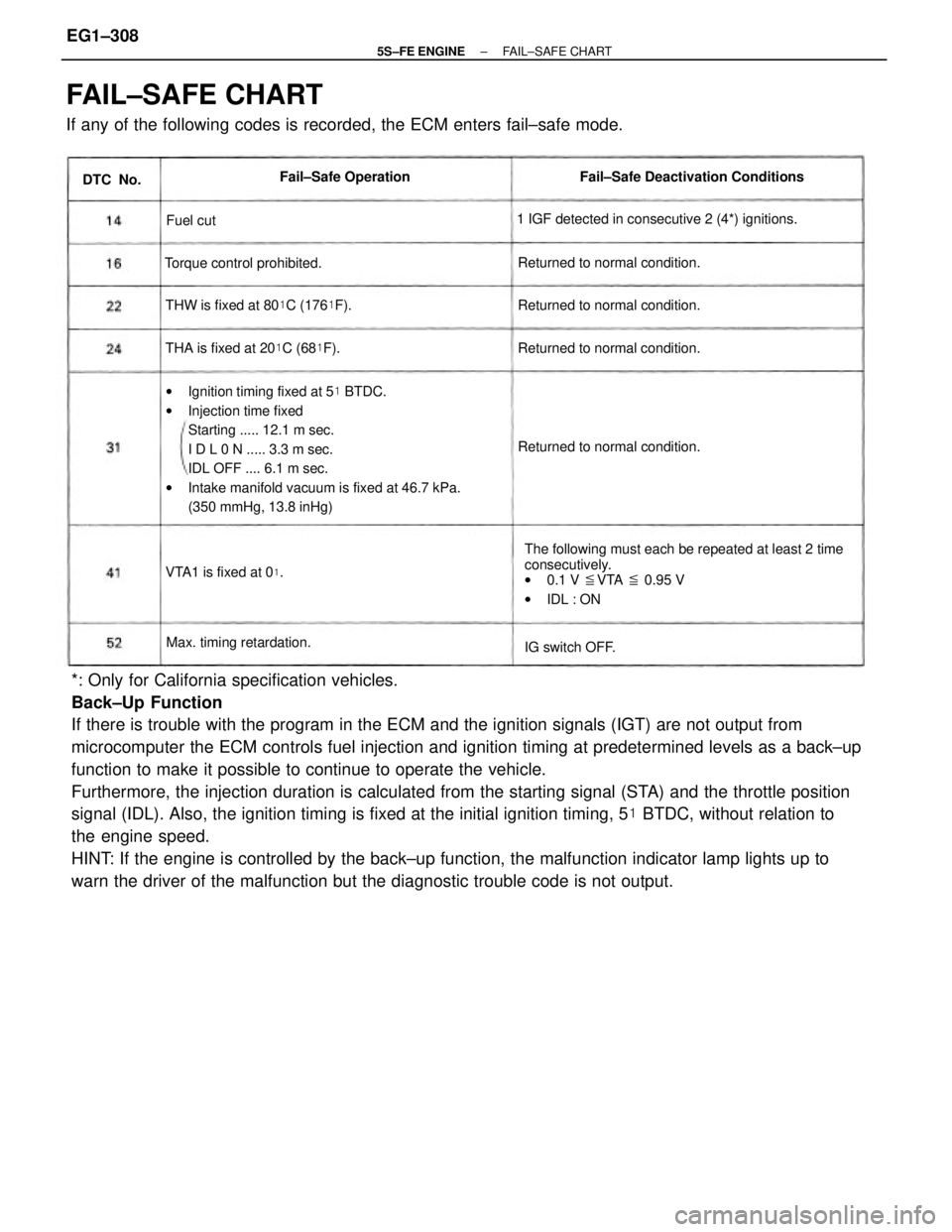
*: Only for California specification vehicles.
Back±Up Function
If there is trouble with the program in the ECM and the ignition signals (IGT) are not output from
microcomputer the ECM controls fuel injection and ignition timing at predetermined levels as a back±up
function to make it possible to continue to operate the vehicle.
Furthermore, the injection duration is calculated from the starting signal (STA) and the throttle position
signal (IDL). Also, the ignition timing is fixed at the initial ignition timing, 5� BTDC, without relation to
the engine speed.
HINT: If the engine is controlled by the back±up function, the malfunction indicator lamp lights up to
warn the driver of the malfunction but the diagnostic trouble code is not output.
FAIL±SAFE CHART
If any of the following codes is recorded, the ECM enters fail±safe mode.
wIgnition timing fixed at 5� BTDC.
wInjection time fixed
Starting ..... 12.1 m sec.
I D L 0 N ..... 3.3 m sec.
IDL OFF .... 6.1 m sec.
wIntake manifold vacuum is fixed at 46.7 kPa.
(350 mmHg, 13.8 inHg)
The following must each be repeated at least 2 time
consecutively.
w0.1 V �VTA � 0.95 V
wIDL : ON 1 IGF detected in consecutive 2 (4*) ignitions.Fail±Safe Deactivation Conditions
THW is fixed at 80�C (176�F).
THA is fixed at 20�C (68�F). Returned to normal condition.Returned to normal condition.
Returned to normal condition. Returned to normal condition. Torque control prohibited.
Max. timing retardation.Fail±Safe Operation
VTA1 is fixed at 0
�.
IG switch OFF. DTC No.
Fuel cut
± 5S±FE ENGINEFAIL±SAFE CHARTEG1±308
Page 403 of 4770
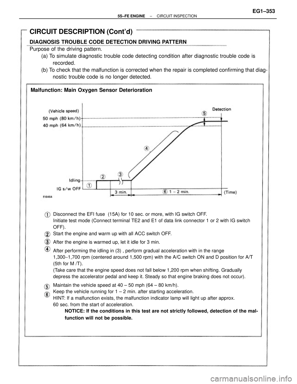
Disconnect the EFI fuse (15A) for 10 sec. or more, with IG switch OFF.
Initiate test mode (Connect terminal TE2 and E1 of data link connector 1 or 2 with IG switch
OFF).
Start the engine and warm up with all ACC switch OFF.
After the engine is warmed up, let it idle for 3 min.
After performing the idling in (3) , perform gradual acceleration with in the range
1,300~1,700 rpm (centered around 1,500 rpm) with the A/C switch ON and D position for A/T
(5th for M /T).
(Take care that the engine speed does not fall below 1,200 rpm when shifting. Gradually
depress the accelerator pedal and keep it. Steady so that engine braking does not occur).
Maintain the vehicle speed at 40 ± 50 mph (64 ± 80 km/h).
Keep the vehicle running for 1 ± 2 min. after starting acceleration.
HINT: If a malfunction exists, the malfunction indicator lamp will light up after approx.
60 sec. from the start of acceleration.
NOTICE: If the conditions in this test are not strictly followed, detection of the mal-
function will not be possible.
CIRCUIT DESCRIPTION (Cont'd)
DIAGNOSIS TROUBLE CODE DETECTION DRIVING PATTERN
Purpose of the driving pattern.
(a) To simulate diagnostic trouble code detecting condition after diagnostic trouble code is
recorded.
(b) To check that the malfunction is corrected when the repair is completed confirming that diag-
nostic trouble code is no longer detected.
Malfunction: Main Oxygen Sensor Deterioration
± 5S±FE ENGINECIRCUIT INSPECTIONEG1±353
Page 414 of 4770
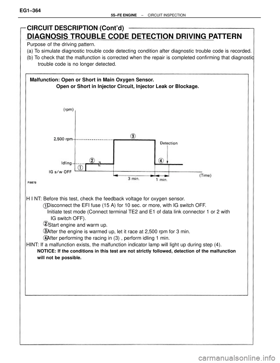
H I NT: Before this test, check the feedback voltage for oxygen sensor.
Disconnect the EFI fuse (15 A) for 10 sec. or more, with IG switch OFF.
Initiate test mode (Connect terminal TE2 and E1 of data link connector 1 or 2 with
IG switch OFF).
Start engine and warm up.
After the engine is warmed up, let it race at 2,500 rpm for 3 min.
After performing the racing in (3) , perform idling 1 min.
HINT: If a malfunction exists, the malfunction indicator lamp will light up during step (4).
NOTICE: If the conditions in this test are not strictly followed, detection of the malfunction
will not be possible.
CIRCUIT DESCRIPTION (Cont'd)
DIAGNOSIS TROUBLE CODE DETECTION DRIVING PATTERN
Purpose of the driving pattern.
(a) To simulate diagnostic trouble code detecting condition after diagnostic trouble code is recorded.
(b) To check that the malfunction is corrected when the repair is completed confirming that diagnostic
trouble code is no longer detected.
Malfunction: Open or Short in Main Oxygen Sensor.
Open or Short in Injector Circuit, Injector Leak or Blockage.
± 5S±FE ENGINECIRCUIT INSPECTIONEG1±364
Page 420 of 4770

Disconnect the E F I fuse (15 A) for 10 sec. or more, with IG switch OFF.
Initiate test mode (Connect terminals TE2 and E1 of data link connector 1 or 2
with I G switch OFF).
Start the engine and warm up, with all ACC switch OFF.
After the engine is warmed up, let it drive at 50 ~ 55 mph (80 ~ 88 km/h)
for 10 min. or more.
After driving, stop at a safe place and perform idling for 2 min. or less.
After performing the idling in (4) , perform acceleration to 60 mph (96 km/h)
with the throttle valve fully open.
HINT: If a malfunction exists, the malfunction indicator lamp will light up during
step.
NOTICE: If the conditions in this test are not strictly followed, detection of the
malfunction will not be possible.
CIRCUIT DESCRIPTION (Cont'd)
DIAGNOSIS TROUBLE CODE DETECTION DRIVING PATTERN
Purpose of the driving pattern.
(a) To simulate diagnostic trouble code detecting condition after diagnostic trouble code is
recorded.
(b) To check that the malfunction is corrected when the repair is completed confirming that diagnos±
tic trouble code is no longer detected.
Malfunction: Open or Short in Sub Oxygen Sensor
± 5S±FE ENGINECIRCUIT INSPECTIONEG1±370
Page 441 of 4770

Disconnect the EFI fuse (15 A) for 10 sec. or more, with IG switch OFF. Initiate
test mode (Connect terminals TE2 and E1 of data link connector, 1 or 2 with IG
switch OFF).
CIRCUIT DESCRIPTION (Cont'd)
DIAGNOSIS TROUBLE CODE DETECTION DRIVING PATTERN
Purpose of the driving pattern.
(a) To simulate diagnostic trouble code detecting condition after diagnostic trouble code is
recorded.
(b) To check that the malfunction is corrected when the repair is completed confirming that diag-
nostic trouble code is no longer detected.
Malfunction: Open in EGR gas temp. sensor circuit
Start the engine and warm up.
After the engine is warmed up, let it idle for 3 min.
With the A/C ON and transmission in 5th gear A/T in ªDº position), drive at
55 ± 60 mph (88 ± 96 km/h) for 4 min. or less.
HINT: If a malfunction exists, the malfunction indicator lamp will light up dur-
ing step (4) .
NOTICE: If the conditions in this test are not strictly observed, detection of
the malfunction will not be possible.
± 5S±FE ENGINECIRCUIT INSPECTIONEG1±391
Page 450 of 4770
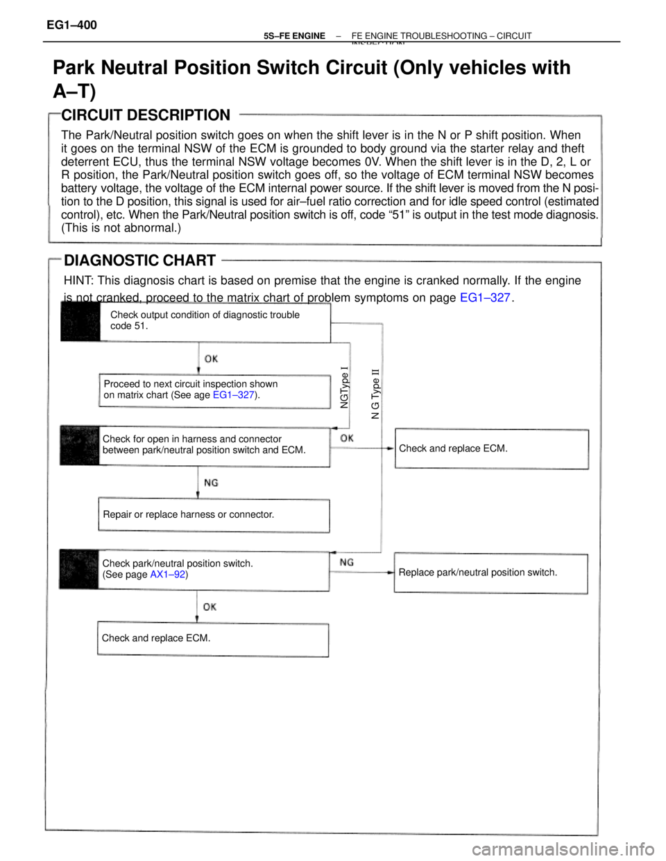
CIRCUIT DESCRIPTION
The Park/Neutral position switch goes on when the shift lever is in the N or P shift position. When
it goes on the terminal NSW of the ECM is grounded to body ground via the starter relay and theft
deterrent ECU, thus the terminal NSW voltage becomes 0V. When the shift lever is in the D, 2, L or
R position, the Park/Neutral position switch goes off, so the voltage of ECM terminal NSW becomes
battery voltage, the voltage of the ECM internal power source. If the shift lever is moved from the N posi-
tion to the D position, this signal is used for air±fuel ratio correction and for idle speed control (estimated
control), etc. When the Park/Neutral position switch is off, code ª51º is output in the test mode diagnosis.
(This is not abnormal.)
Park Neutral Position Switch Circuit (Only vehicles with
A±T)
Check for open in harness and connector
between park/neutral position switch and ECM.Check output condition of diagnostic trouble
code 51.
Proceed to next circuit inspection shown
on matrix chart (See age EG1±327).
Check park/neutral position switch.
(See page AX1±92) Repair or replace harness or connector.
Replace park/neutral position switch.Check and replace ECM.
Check and replace ECM.
N G Type II NGType I
DIAGNOSTIC CHART
HINT: This diagnosis chart is based on premise that the engine is cranked normally. If the engine
is not cranked, proceed to the matrix chart of problem symptoms on page EG1±327.
± 5S±FE ENGINEFE ENGINE TROUBLESHOOTING ± CIRCUITINSPECTION
EG1±400
Page 503 of 4770

22
INTERIOR
�Layout of Audio System�
� TILT STEERING
�The tilt steering is standard on all models.
�The steering wheel position can be changed to any of 6 positions..
� POWER WINDOW SYSTEM
A power window system is standard on the LE and XLE grade models and optional on the CE grade model. The power
window system includes one±touch auto down and key±off operation functions. The one±touch auto down function
automatically opens the driver's side window fully. The key±off operation function makes it possible to operate the
power windows for approximately 45 seconds after the ignition key is turned to the ACC or LOCK position, if the
front doors are not opened.
� DOOR LOCK CONTROL SYSTEM
�The door lock control system with 2±step unlock function is standard on the LE and XLE grade model and optional
as a set with the power window system on the CE grade model. With the 2±step function, turning the key once in
the driver's door unlocks the driver's door only. Turning it twice unlocks all the doors.
�A key confinement prevention function is provided. When the door is opened and the door lock button is locked
with the key still inserted in the ignition key cylinder, the key confinement prevention mechanism immediately
turns the door lock button to unlock. This prevents the key from being inadvertently locked inside the vehicle.