Page 4698 of 4770
Toyota Supports ASE CertificationPage 1 of 1
SU001±00Title:
FRONT SUSPENSION SUPPORT NOISE
Models:
'97 ± '99 Avalon & '97 ± '00 Camry
Technical Service
BULLETIN
January 21, 2000
TSB Update Notice:
The information contained in this TSB updates SU002±99 dated September 3, 1999.
Revised text is red
and underlined.
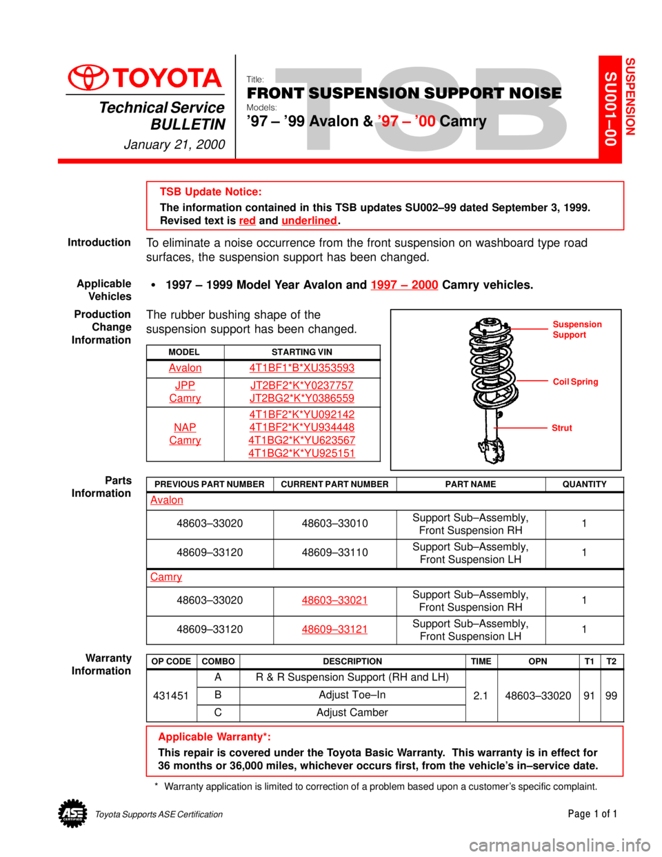
To eliminate a noise occurrence from the front suspension on washboard type road
surfaces, the suspension support has been changed.
�1997 ± 1999 Model Year Avalon and 1997 ± 2000
Camry vehicles.
The rubber bushing shape of the
suspension support has been changed.
MODELSTARTING VIN
Avalon4T1BF1*B*XU353593
JPP
Camry
JT2BF2*K*Y0237757
JT2BG2*K*Y0386559
NAP
Camry
4T1BF2*K*YU092142
4T1BF2*K*YU934448
4T1BG2*K*YU623567
4T1BG2*K*YU925151
PREVIOUS PART NUMBERCURRENT PART NUMBERPART NAMEQUANTITY
Avalon
48603±3302048603±33010Support Sub±Assembly,
Front Suspension RH1
48609±3312048609±33110Support Sub±Assembly,
Front Suspension LH1
Camry
48603±3302048603±33021Support Sub±Assembly,
Front Suspension RH1
48609±3312048609±33121Support Sub±Assembly,
Front Suspension LH1
OP CODECOMBODESCRIPTIONTIMEOPNT1T2
AR & R Suspension Support (RH and LH)
431451BAdjust Toe±In2.148603±330209199
CAdjust Camber
Applicable Warranty*:
This repair is covered under the Toyota Basic Warranty. This warranty is in effect for
36 months or 36,000 miles, whichever occurs first, from the vehicle's in±service date.
* Warranty application is limited to correction of a problem based upon a customer's specific complaint.
SUSPENSION
Introduction
Applicable
Vehicles
Production
Change
Information
Suspension
Support
Coil Spring
Strut
Parts
Information
Warranty
Information
Page 4699 of 4770
Toyota Supports ASE CertificationPage 1 of 2
SU001-02Title:
REAR BEARING O-RING SERVICE TIP
Models:
'97 ± '01 Camry, '00 ± '02 Avalon &
'99 ± '02 Solara
Technical Service
BULLETIN
March 1, 2002
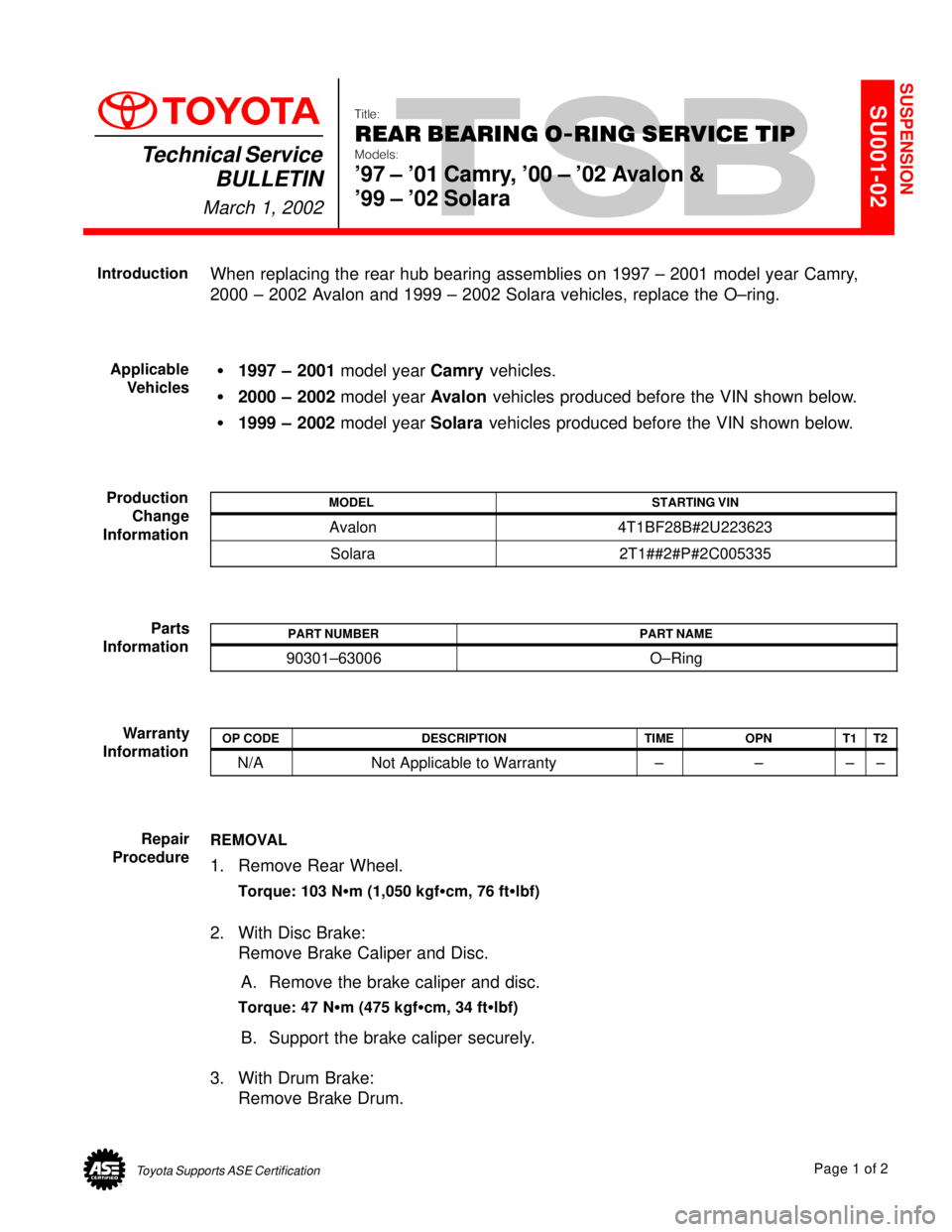
When replacing the rear hub bearing assemblies on 1997 ± 2001 model year Camry,
2000 ± 2002 Avalon and 1999 ± 2002 Solara vehicles, replace the O±ring.
�1997 ± 2001 model year Camry vehicles.
�2000 ± 2002 model year Avalon vehicles produced before the VIN shown below.
�1999 ± 2002 model year Solara vehicles produced before the VIN shown below.
MODELSTARTING VIN
Avalon4T1BF28B#2U223623
Solara2T1##2#P#2C005335
PART NUMBERPART NAME
90301±63006O±Ring
OP CODEDESCRIPTIONTIMEOPNT1T2
N/ANot Applicable to Warranty±±±±
REMOVAL
1. Remove Rear Wheel.
Torque: 103 N�m (1,050 kgf�cm, 76 ft�lbf)
2. With Disc Brake:
Remove Brake Caliper and Disc.
A. Remove the brake caliper and disc.
Torque: 47 N�m (475 kgf�cm, 34 ft�lbf)
B. Support the brake caliper securely.
3. With Drum Brake:
Remove Brake Drum.
SUSPENSION
Introduction
Applicable
Vehicles
Production
Change
Information
Parts
Information
Warranty
Information
Repair
Procedure
Page 4701 of 4770
Toyota Supports ASE CertificationPage 1 of 1
SU002±99Title:
FRONT SUSPENSION SUPPORT NOISE
Models:
'97 ± '99 Avalon & Camry
Technical Service
BULLETIN
September 3, 1999
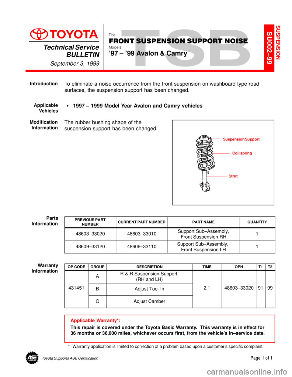
To eliminate a noise occurrence from the front suspension on washboard type road
surfaces, the suspension support has been changed.
�1997 ± 1999 Model Year Avalon and Camry vehicles
The rubber bushing shape of the
suspension support has been changed.
PREVIOUS PART
NUMBERCURRENT PART NUMBERPART NAMEQUANTITY
48603±3302048603±33010Support Sub±Assembly,
Front Suspension RH1
48609±3312048609±33110Support Sub±Assembly,
Front Suspension LH1
OP CODEGROUPDESCRIPTIONTIMEOPNT1T2
AR & R Suspension Support
(RH and LH)
431451BAdjust Toe±In2.148603±330209199
CAdjust Camber
Applicable Warranty*:
This repair is covered under the Toyota Basic Warranty. This warranty is in effect for
36 months or 36,000 miles, whichever occurs first, from the vehicle's in±service date.
* Warranty application is limited to correction of a problem based upon a customer's specific complaint.
SUSPENSION
Introduction
Applicable
Vehicles
Modification
Information
Suspension Support
Coil spring
Strut
Parts
Information
Warranty
Information
Page 4704 of 4770
Toyota Supports ASE CertificationPage 1 of 1
TC002±99Title:
REVISED DRIVE SHAFT GREASE
Models:
RAV4, Tercel, Corolla, Celica, Camry & Supra
Technical Service
BULLETIN
April 9, 1999
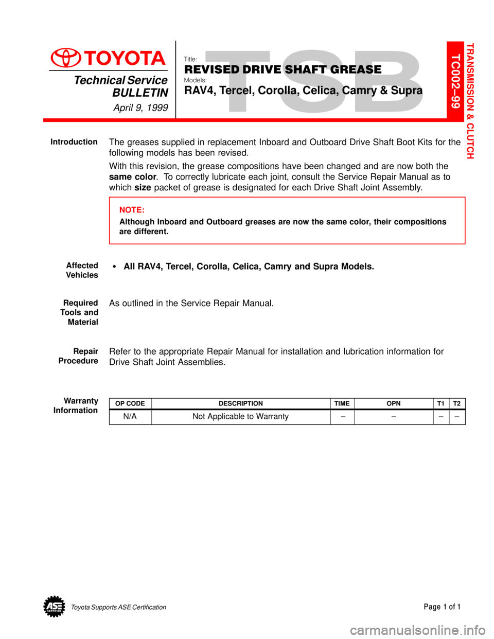
The greases supplied in replacement Inboard and Outboard Drive Shaft Boot Kits for the
following models has been revised.
With this revision, the grease compositions have been changed and are now both the
same color. To correctly lubricate each joint, consult the Service Repair Manual as to
which size packet of grease is designated for each Drive Shaft Joint Assembly.
NOTE:
Although Inboard and Outboard greases are now the same color, their compositions
are different.
�All RAV4, Tercel, Corolla, Celica, Camry and Supra Models.
As outlined in the Service Repair Manual.
Refer to the appropriate Repair Manual for installation and lubrication information for
Drive Shaft Joint Assemblies.
OP CODEDESCRIPTIONTIMEOPNT1T2
N/ANot Applicable to Warranty ±±±±
TRANSMISSION & CLUTCH
Introduction
Affected
Vehicles
Required
Tools and
Material
Repair
Procedure
Warranty
Information
Page 4712 of 4770
Toyota Supports ASE CertificationPage 1 of 1
TC003±99Title:
AUTOMATIC TRANSMISSION FLUIDS
Models:
All Models
Technical Service
BULLETIN
May 21, 1999
REVISION NOTICE:
The information contained in this TSB updates TC003±98 dated June 19, 1998.
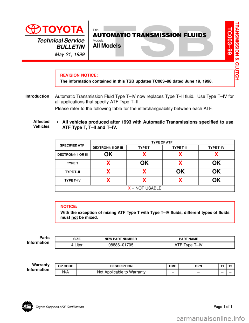
Automatic Transmission Fluid Type T±IV now replaces Type T±II fluid. Use Type T±IV for
all applications that specify ATF Type T±II.
Please refer to the following table for the interchangeability between each ATF.
�All vehicles produced after 1993 with Automatic Transmissions specified to use
ATF Type T, T±II and T±IV.
SPECIFIED ATFTYPE OF ATFSPECIFIED ATFDEXTRON) II OR IIITYPE TTYPE T±IITYPE T±IV
DEXTRON) II OR IIIOKXXX
TYPE TXOKXOK
TYPE T±IIXXOKOK
TYPE T±IVXXXOK
X = NOT USABLE
NOTICE:
With the exception of mixing ATF Type T with Type T±IV fluids, different types of fluids
must not
be mixed.
SIZENEW PART NUMBERPART NAME
4 Liter08886±01705ATF Type T±IV
OP CODEDESCRIPTIONTIMEOPNT1T2
N/ANot Applicable to Warranty ±±±±
TRANSMISSION & CLUTCH
Introduction
Affected
Vehicles
Parts
Information
Warranty
Information
Page 4718 of 4770
Toyota Supports ASE CertificationPage 1 of 43
SS002-03Title:
O2S TEST RESULTS (MODE 05)
Models:
All '96 ± '03, '04 Corolla, ECHO, Matrix, Sienna
& Scion xA & xBTechnical Service
BULLETIN
December 17, 2003
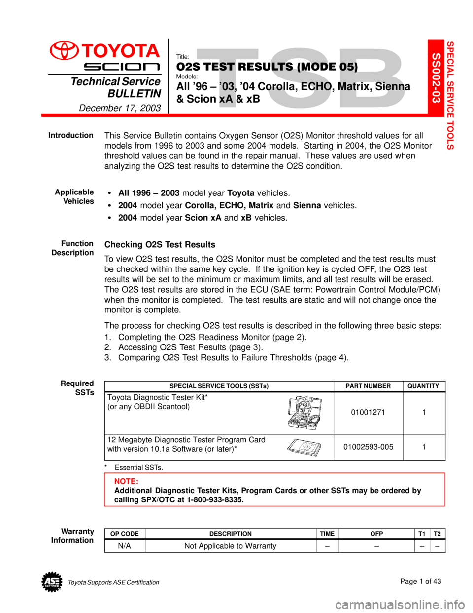
This Service Bulletin contains Oxygen Sensor (O2S) Monitor threshold values for all
models from 1996 to 2003 and some 2004 models. Starting in 2004, the O2S Monitor
threshold values can be found in the repair manual. These values are used when
analyzing the O2S test results to determine the O2S condition.
�All 1996 ± 2003 model year Toyota vehicles.
�2004 model year Corolla, ECHO, Matrix and Sienna vehicles.
�2004 model year Scion xA and xB vehicles.
Checking O2S Test Results
To view O2S test results, the O2S Monitor must be completed and the test results must
be checked within the same key cycle. If the ignition key is cycled OFF, the O2S test
results will be set to the minimum or maximum limits, and all test results will be erased.
The O2S test results are stored in the ECU (SAE term: Powertrain Control Module/PCM)
when the monitor is completed. The test results are static and will not change once the
monitor is complete.
The process for checking O2S test results is described in the following three basic steps:
1. Completing the O2S Readiness Monitor (page 2).
2. Accessing O2S Test Results (page 3).
3. Comparing O2S Test Results to Failure Thresholds (page 4).
SPECIAL SERVICE TOOLS (SSTs)PART NUMBERQUANTITY
Toyota Diagnostic Tester Kit*
(or any OBDII Scantool)
010012711
12 Megabyte Diagnostic Tester Program Card
with version 10.1a Software (or later)*01002593-0051
* Essential SSTs.
NOTE:
Additional Diagnostic Tester Kits, Program Cards or other SSTs may be ordered by
calling SPX/OTC at 1-800-933-8335.
OP CODEDESCRIPTIONTIMEOFPT1T2
N/ANot Applicable to Warranty±±±±
SPECIAL SERVICE TOOLS
Introduction
Applicable
Vehicles
Function
Description
Required
SSTs
Warranty
Information
Page 4721 of 4770
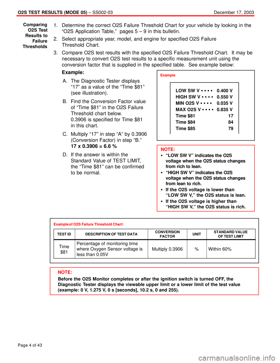
NOTE:
Before the O2S Monitor completes or after the ignition switch is turned OFF, the
Diagnostic Tester displays the viewable upper limit or a lower limit of the test value
(example: 0 V, 1.275 V, 0 s [seconds], 10.2 s, 0 and 255).
O2S TEST RESULTS (MODE 05) ± SS002-03December 17, 2003
Page 4 of 43
1. Determine the correct O2S Failure Threshold Chart for your vehicle by looking in the
ªO2S Application Table,º pages 5 ± 9 in this bulletin.
2. Select appropriate year, model, and engine for specified O2S Failure
Threshold Chart.
3. Compare O2S test results with the specified O2S Failure Threshold Chart. It may be
necessary to convert O2S test results to a specific measurement unit using the
conversion factor that is supplied in the specified table. See example below:
Example:
A. The Diagnostic Tester displays
ª17º as a value of the ªTime $81º
(see illustration).
B. Find the Conversion Factor value
of ªTime $81º in the O2S Failure
Threshold chart below.
0.3906 is specified for Time $81
in this chart.
C. Multiply ª17º in step ªAº by 0.3906
(Conversion Factor) in step ªB.º
17 x 0.3906 = 6.6 %
D. If the answer is within the
Standard Value of TEST LIMIT,
the ªTime $81º can be confirmed
to be normal.
Example of O2S Failure Threshold Chart:
TEST ID
DESCRIPTION OF TEST DATACONVERSION
FACTORUNITSTANDARD VALUE
OF TEST LIMIT
Time
$81Percentage of monitoring time
where Oxygen Sensor voltage is
less than 0.05V
Multiply 0.3906%Within 60%
Comparing
O2S Test
Results to
Failure
Thresholds
Example
LOW SW V � � � � 0.400 V
HIGH SW V � � � � 0.550 V
MIN O2S V � � � �0.035 V
MAX O2S V � � � �0.835 V
Time $81 17
Time $84 84
Time $85 79
NOTE:
�ªLOW SW Vº indicates the O2S
voltage when the O2S status changes
from rich to lean.
�ªHIGH SW Vº indicates the O2S
voltage when the O2S status changes
from lean to rich.
�If the O2S voltage is lower than
ªLOW SW V,º the O2S status is lean.
�If the O2S voltage is higher than
ªHIGH SW V,º the O2S status is rich.
Page 4727 of 4770

O2S TEST RESULTS (MODE 05) ± SS002-03December 17, 2003
Page 10 of 43
CHART 1:
Front O2S (Bank 1 Sensor 1 and Bank 2 Sensor 1) Voltage Monitor
Related DTCs: P0130, P0150, P2195, P2196, P2197 and P2198
TEST IDDESCRIPTION OF TEST DATACONVERSION
FACTORUNITSTANDARD VALUE
OF TEST LIMIT
Time
$07The minimum voltage during O2S
monitoringN/AVBetween 0 and 0.4 V
Time
$08The maximum voltage during
O2S monitoringN/AVBetween 0.55 and
1.275 V
If the sensor voltage is out of the standard value, the ECM interprets this as a malfunction.
Front O2S (Bank 1 Sensor 1 and Bank 2 Sensor 1) Response Monitor
Related DTCs: P0133 and P0153
TEST IDDESCRIPTION OF TEST DATACONVERSION
FACTORUNITSTANDARD VALUE
OF TEST LIMIT
Time
$31Time to change from Lean
(30.4 V) to Rich (.0.55 V)N/ASecondBetween 0 and
1 second
Time
$32Time to change from Rich
(.0.55 V) to Lean (.0.4 V)N/ASecondBetween 0 and
1 second
If the time required to change is out of the standard value, the ECM interprets this as a malfunction.
Rear O2S (Bank 1 Sensor 2 and Bank 2 Sensor 2) Voltage Monitor
Related DTCs: P0136 and P0156
TEST IDDESCRIPTION OF TEST DATACONVERSION
FACTORUNITSTANDARD VALUE
OF TEST LIMIT
Time
$07The minimum voltage during O2S
monitoringN/AVBetween 0 and 0.4 V
Time
$08The maximum voltage during
O2S monitoringN/AVBetween 0.5 and
1.275 V
If the sensor voltage is out of the standard value, the ECM interprets this as a malfunction. O2S
Failure
Threshold
Charts