Page 4306 of 4770
 Torque the 4 column assembly set nuts.
Torque:")
SR06M±01
W03303
Matchmarks
W02655
Mark SR±16
± STEERINGTILT STEERING COLUMN
2111 Author�: Date�:
INSTALLATION
1. INSTALL STEERING COLUMN ASSEMBLY
(a) Torque the 4 column assembly set nuts.
Torque: 25 N´m (260 kgf´cm, 19 ft´lbf)
(b) Connect the connectors.
2. INSTALL INTERMEDIATE SHAFT ASSEMBLY
Torque the bolt.
Torque: 35 N´m (360 kgf´cm, 26 ft´lbf)
3. CONNECT INTERMEDIATE SHAFT ASSEMBLY
(a) Align the matchmarks on the intermediate shaft and con-
trol valve shaft.
(b) Torque the bolt.
Torque: 35 N´m (360 kgf´cm, 26 ft´lbf)
4. INSTALL SPIRAL CABLE
(See page BE±23)
5. INSTALL COMBINATION SWITCH WITH SPIRAL
CABLE
(a) Tighten the 3 screws.
(b) Connect the airbag connector.
(c) Connect the 3 connectors.
6. INSTALL LOWER INSTRUMENT FINISH PANEL
7. INSTALL LH LOWER INSTRUMENT PANEL
Tighten the 4 bolts.
8. INSTALL No.1 LOWER INSTRUMENT PANEL
(a) Connect the hood lock control cable.
(b) Tighten the 2 screws.
9. INSTALL COWL SIDE TRIM
Install the clip.
10. INSTALL FRONT DOOR INSIDE SCUFF PLATE
11. INSTALL UPPER AND LOWER COLUMN COVERS
(a) Tighten the 3 screws.
(b) Install the lower No.2 cover to the lower cover.
12. CENTER SPIRAL CABLE
(a) Check that the front wheels are facing straight ahead.
(b) Turn the cable counterclockwise by hand until it becomes
harder to turn the cable.
(c) Then rotate the cable clockwise about 3 turns to align the
mark.
HINT:
The cable will rotate about 3 turns to either left or right of the
center.
Page 4322 of 4770
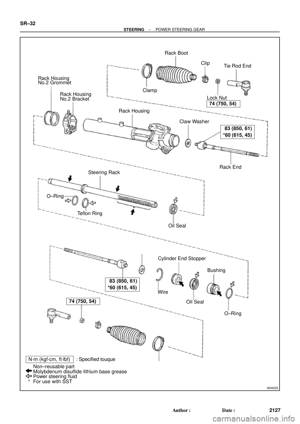
W04225
Rack Housing
No.2 Grommet
Rack Housing
No.2 Bracket
Rack Housing
� Claw Washer
Rack End Lock NutTie Rod End Rack Boot
� ClampClip
Steering Rack
� Teflon Ring
� Oil Seal
Cylinder End Stopper
Bushing
� O±Ring � Oil Seal � Wire �
�
N´m (kgf´cm, ft´lbf) : Specified touque
Power steering fluid
For use with SST Non±reusable part
Molybdenum disulfide lithium base grease �
*
74 (750, 54)
83 (850, 61)
*60 (615, 45)
83 (850, 61)
*60 (615, 45)
74 (750, 54)
� O±Ring SR±32
± STEERINGPOWER STEERING GEAR
2127 Author�: Date�:
Page 4323 of 4770
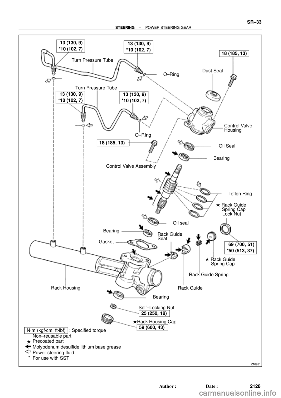
Z18921
Turn Pressure Tube
� O±RingDust Seal
Turn Pressure Tube
� O±RIngControl Valve
Housing
� Oil Seal
� Bearing
� Teflon Ring
� Rack Guide
Spring Cap
Lock Nut
� Rack Guide
Spring Cap
Rack Guide Spring
Rack Guide
� Self±Locking Nut� Bearing
�Rack Housing Cap
N´m (kgf´cm, ft´lbf) : Specified torque
Non±reusable part
Precoated part
Molybdenum desulfide lithium base grease
Power steering fluid
For use with SSTRack Housing� Bearing
� GasketControl Valve Assembly � �
13 (130, 9)
*10 (102, 7) 13 (130, 9)
*10 (102, 7)
18 (185, 13)
69 (700, 51)
*50 (513, 37)
25 (250, 18)
59 (600, 43)
18 (185, 13)
13 (130, 9)
*10 (102, 7) 13 (130, 9)
*10 (102, 7)
�
�
*Rack Guide
Seat� Oil seal
± STEERINGPOWER STEERING GEAR
SR±33
2128 Author�: Date�:
Page 4325 of 4770
SR06V±01
W04228
SST
W04229
SST
R00429
Matchmarks
W04230
R11644
Claw Washer
± STEERINGPOWER STEERING GEAR
SR±35
2130 Author�: Date�:
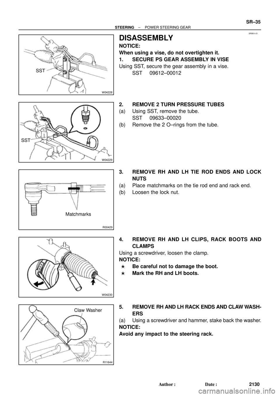
DISASSEMBLY
NOTICE:
When using a vise, do not overtighten it.
1. SECURE PS GEAR ASSEMBLY IN VISE
Using SST, secure the gear assembly in a vise.
SST 09612±00012
2. REMOVE 2 TURN PRESSURE TUBES
(a) Using SST, remove the tube.
SST 09633±00020
(b) Remove the 2 O±rings from the tube.
3. REMOVE RH AND LH TIE ROD ENDS AND LOCK
NUTS
(a) Place matchmarks on the tie rod end and rack end.
(b) Loosen the lock nut.
4. REMOVE RH AND LH CLIPS, RACK BOOTS AND
CLAMPS
Using a screwdriver, loosen the clamp.
NOTICE:
�Be careful not to damage the boot.
�Mark the RH and LH boots.
5. REMOVE RH AND LH RACK ENDS AND CLAW WASH-
ERS
(a) Using a screwdriver and hammer, stake back the washer.
NOTICE:
Avoid any impact to the steering rack.
Page 4326 of 4770
 Using a spanner (24 mm)")
R11645
SST
R11646
SSTRack Guide
Spring Cap Lock Nut
R11647
Rack Guide
Spring Cap
SST
R11648
SST
R11553
Matchmarks SR±36
± STEERINGPOWER STEERING GEAR
2131 Author�: Date�:
(b) Using a spanner (24 mm) to hold the steering rack steady,
and using SST, remove the rack end.
SST 09922±10010
NOTICE:
�Use SST 09922±10010 in the direction shown in the il-
lustration.
�Mark the RH and LH rack ends.
(c) Remove the washer from the rack end.
6. REMOVE RACK GUIDE SPRING CAP LOCK NUT
Using SST, remove the nut.
SST 09922±10010
NOTICE:
Use SST 09922±10010 in the direction shown in the illustra-
tion.
7. REMOVE RACK GUIDE SPRING CAP, RACK GUIDE
SPRING, RACK GUIDE AND RACK GUIDE SEAT
(a) Using SST, remove the cap.
SST 09631±10021
(b) Remove the seat from the guide.
8. REMOVE RACK HOUSING CAP
9. REMOVE SELF±LOCKING NUT
Using SST to stop the control valve shaft rotating, remove the
nut.
SST 09616±00010
10. REMOVE DUST COVER
11. REMOVE CONTROL VALVE HOUSING WITH CON-
TROL VALVE ASSEMBLY
(a) Place matchmarks on the valve housing and rack hous-
ing.
(b) Remove the 2 bolts.
(c) Remove the gasket from the rack housing.
Page 4327 of 4770
 To prevent")
R11554
Vinyl Tape
Shop RagPress
R11649
Matchmarks
R11650
R11651
Cylinder End
StopperWire
SST
± STEERINGPOWER STEERING GEAR
SR±37
2132 Author�: Date�:
12. REMOVE CONTROL VALVE ASSEMBLY
(a) To prevent oil seal lip damage, wind vinyl tape on the ser-
rated part of the valve shaft.
(b) Press out the valve assembly with the oil seal.
NOTICE:
�Place a shop rag between the valve housing and the
blocks.
�Be careful not to drop the valve assembly.
�Be careful not to damage the oil seal lip.
13. REMOVE OIL SEAL
Remove the oil seal from the control valve assembly.
14. REMOVE RACK HOUSING NO.2 BRACKET AND
GROMMET
(a) Place matchmarks on the bracket and rack housing.
(b) Using a screwdriver, pry the clamp of the bracket.
(c) Remove the grommet from the bracket.
15. REMOVE CYLINDER END STOPPER
(a) Using SST, turn the stopper clockwise until the wire end
is visible through the service hole.
SST 09631±10021
(b) Using SST, turn the stopper counterclockwise, and re-
move the wire.
SST 09631±10021
Page 4334 of 4770
 Align the installation ho")
R11656
SST
Wire
Cylinder End
Stopper
R00662
SST
R11657
R11658
R11575
Vinyl Tape SR±44
± STEERINGPOWER STEERING GEAR
2139 Author�: Date�:
5. INSTALL CYLINDER END STOPPER
(a) Align the installation hole for the wire of the stopper with
the slot of the rack housing.
(b) Install a new wire into the stopper.
(c) Using SST, turn the stopper clockwise 450 ± 50°.
SST 09631±10021
6. AIR TIGHTNESS TEST
(a) Install SST to the rack housing.
SST 09631±12071
(b) Apply 53 kPa (400 mmHg, 15.75 in.Hg) of vacuum for
about 30 seconds.
(c) Check that there is no change in the vacuum.
If there is change in the vacuum, check the installation of the oil
seals.
7. INSTALL RACK HOUSING NO.2 BRACKET AND
GROMMET
(a) Install the grommet to the bracket.
HINT:
Align the projection of the grommet with the hole of the bracket.
(b) Align the matchmarks on the bracket and rack housing.
(c) Place the bracket in a vise and tighten the vise to fasten
the clamp.
8. INSTALL CONTROL VALVE ASSEMBLY
(a) To prevent oil seal lip damage, wind vinyl tape on the ser-
rated part of the valve shaft.
(b) Coat the teflon rings with power steering fluid.
(c) Install the valve assembly into the valve housing.
NOTICE:
Be careful not to damage the teflon rings and oil seal.
Page 4335 of 4770
 Coat a new oil seal lip with power steering fluid.
(b) Using SST, pr")
W03562Oil Seal SST Press
R11648
SST
R11659
Punch
± STEERINGPOWER STEERING GEAR
SR±45
2140 Author�: Date�:
9. INSTALL OIL SEAL
(a) Coat a new oil seal lip with power steering fluid.
(b) Using SST, press in the oil seal.
SST 09612±22011
NOTICE:
Make sure to install the oil seal facing the correct direction.
10. INSTALL CONTROL VALVE HOUSING WITH CON-
TROL VALVE ASSEMBLY
(a) Place a new gasket on the rack housing.
(b) Align the matchmarks on the valve housing and rack
housing.
(c) Torque the 2 bolts.
Torque: 18 N´m (185 kgf´cm, 13 ft´lbf)
11. INSTALL SELF±LOCKING NUT
Using SST to stop the control valve shaft rotating, torque a new
nut.
SST 09616±00010
Torque: 25 N´m (250 kgf´cm, 18 ft´lbf)
12. INSTALL DUST COVER
13. INSTALL RACK HOUSING CAP
(a) Apply sealant to 2 or 3 threads of the cap.
Sealant:
Part No.08833±00080, THREE BOND 1344,
LOCTITE 242 or equivalent
(b) Torque the cap.
Torque: 59 N´m (600 kgf´cm, 43 ft´lbf)
(c) Using a punch and hammer, stake the 2 parts of the cap.
14. INSTALL RACK GUIDE SEAT, RACK GUIDE, RACK
GUIDE SPRING AND RACK GUIDE SPRING CAP
(a) Install the seat to the guide.
(b) Apply sealant to 2 or 3 threads of the cap.
Sealant:
Part No.08833±00080, THREE BOND 1344,
LOCTITE 242 or equivalent
(c) Temporarily install the cap.