Page 4023 of 4770

SS04X±01
± SERVICE SPECIFICATIONSSUSPENSION AND AXLE
SS±61
224 Author�: Date�:
TORQUE SPECIFICATION
Part tightenedN´mkgf´cmft´lbf
FRONT:
Hub nut1031,05076
Tie rod end lock nut7475054
Steering knuckle x Shock absorber2112,150156
Steering knuckle x Brake caliper1071,09079
Steering knuckle x Tie rod end4950036
Axle hub x Drive shaft2943,000217
Lower ball joint x Lower suspension arm1271,30094
Lower ball joint x Steering knuckle1231,25090
Steering knuckle x Disc brake dust cover8.38574 in.´lbf
Drive shaft center bearing lock bolt3233024
Suspension support x Body8082059
Suspension support x Piston rod4950036
ABS speed sensor set bolt8.08271 in.´lbf
Flexible hose and ABS speed sensor wire harness x Shock absorber2930022
Lower suspension arm set bolt2062,100152
Stabilizer bar bracket x Suspension member1919514
Stabilizer bar link set bolt3940029
REAR:
Hub nut1031,05076
No.2 lower suspension arm lock nut5657041
Brake caliper x Rear axle carrier4747534
Axle hub bearing set bolt8082059
Shock absorber x Rear axle carrier New nut
Reused nut (apply engine oil the threads)255
1962,600
2,000188
145
Flexible hose x Shock absorber2930022
ABS speed sensor set bolt8.08271 in.´lbf
ABS speed sensor wire harness x Shock absorber5.55649 in.´lbf
Rear side seatback set bolt1818513
Suspension support x Body3940029
Suspension support x Piston rod4950036
Exhaust center pipe set nut5657041
Parking brake cable set bolt5.45548 in.´lbf
Lower suspension arm x Suspension member1811,850134
Lower suspension arm x Rear axle carrier1811,850134
Strut rod x Body11 31,15083
Strut rod x Rear axle carrier11 31,15083
Suspension member x Body5152038
Suspension member lower stopper sub±assembly x Body3839028
Stabilizer bar bracket x Suspension member1919514
Stabiliser bar link set nut3940029
Page 4342 of 4770
 Check the tires for wear and proper inflation pressu")
R03031
SA078±01
R15157
Front
R07928
SA±2
± SUSPENSION AND AXLETIRE AND WHEEL
1953 Author�: Date�:
TIRE AND WHEEL
INSPECTION
1. INSPECT TIRE
(a) Check the tires for wear and proper inflation pressure.
Cold inflation pressure:
Normal driving
Tire sizeFront, Rear
kPa (kgf/cm2 or bar, psi)
P195/70R14 90S, 90H210 (2.1, 30)
P205/65R15 92H*1 220 (2.2, 32)
*2 200 (2.0, 29)
*1: For all loads including full rated loads
*
2: For reduced loads (1 to 4 passengers)
Trailer towing
Tire sizeFront, Rear
kPa (kgf/cm2 or bar, psi)
P195/70R14 90S*1 210 (2.1, 30)
*2 240 (2.4, 36)
P205/65R15 92H*1 220 (2.2, 32)
*2 240 (2.4, 36)
*1: For driving under 160 km/h (100 mph)
*
2: For driving at 160 km/h (100 mph) or over
(b) Check the tire runout.
Tire runout: 1.0 mm (0.039 in.) or less
2. ROTATING TIRES
HINT:
See the illustration for where to rotate each tire.
3. INSPECT WHEEL BALANCE
(a) Check and adjust the Off±the±car balance.
(b) If necessary, check and adjust the On±the±car balance.
Imbalance after adjustment:
8.0 g (0.018 lb) or less
Page 4343 of 4770
W03084
± SUSPENSION AND AXLETIRE AND WHEEL
SA±3
1954 Author�: Date�:
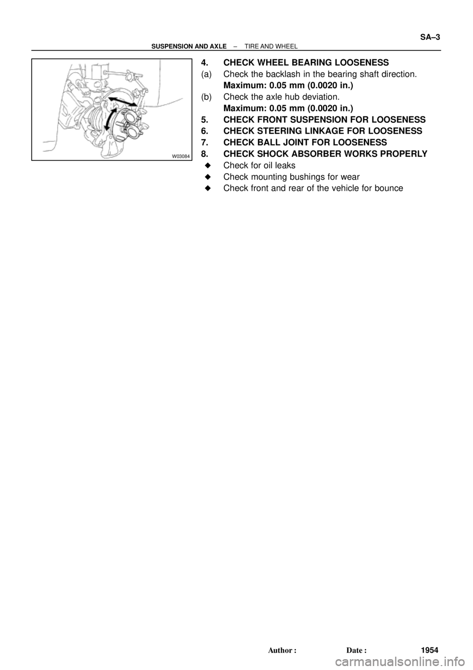
4. CHECK WHEEL BEARING LOOSENESS
(a) Check the backlash in the bearing shaft direction.
Maximum: 0.05 mm (0.0020 in.)
(b) Check the axle hub deviation.
Maximum: 0.05 mm (0.0020 in.)
5. CHECK FRONT SUSPENSION FOR LOOSENESS
6. CHECK STEERING LINKAGE FOR LOOSENESS
7. CHECK BALL JOINT FOR LOOSENESS
8. CHECK SHOCK ABSORBER WORKS PROPERLY
�Check for oil leaks
�Check mounting bushings for wear
�Check front and rear of the vehicle for bounce
Page 4344 of 4770

W03085
Front
R03030
Rear
SA079±01
Z03382
SA3213
AB
C D
Front SA±4
± SUSPENSION AND AXLEFRONT WHEEL ALIGNMENT
1955 Author�: Date�:
FRONT WHEEL ALIGNMENT
INSPECTION
1. MEASURE VEHICLE HEIGHT
Tire sizeFront*1 mm (in.)Rear*2 mm (in.)
195/70R14212 (8.35)264 (10.39)
205/65R15215 (8.46)266 (10.49)
*1: Front measuring point
Measure from the ground to the center of the front side lower
suspension arm mounting bolt.
*
2: Rear measuring point
Measure from the ground to the center of the strut rod mounting
bolt.
NOTICE:
Before inspecting the wheel alignment, adjust the vehicle
height to the specification.
If the vehicle height is not within the specification, try to adjust
it by pushing down on or lifting the body.
2. INSTALL CAMBER±CASTER±KINGPIN GAUGE
ONTO VEHICLE OR POSITION VEHICLE ON WHEEL
ALIGNMENT TESTER
Follow the specific instructions of the equipment manufacturer.
3. INSPECT CAMBER, CASTER AND STEERING AXIS
INCLINATION
5S±FE1MZ±FE
Camber
Left±right error±0°36' ± 45'
(±0.6° ± 0.75°)
45' (0.75°) or less±0°37' ± 45'
(±0.62° ± 0.75°)
45' (0.75°) or less
Caster
Left±right error2°10' ± 45'
(2.17° ± 0.75°)
45' (0.75°) or less2°11' ± 45'
(2.18° ± 0.75°)
45' (0.75°) or less
Steering axis inclination
Left±right error13°01' ± 45'
(13.02° ± 0.75°)
45' (0.75°) or less13°04' ± 45'
(13.07° ± 0.75°)
45' (0.75°) or less
HINT:
If the caster and steering axis inclination are not within the spec-
ification, after the camber has correctly adjusted, recheck the
suspension parts for damaged and/or worn out parts.
4. INSPECT TOE±IN
Toe±in
(Total)A + B: 0° ± 12' (0° ± 0.2°)
C ± D: 0 ± 2 mm (0 ± 0.08 in.)
If the toe±in is not within the specification, adjust it at the rack
ends.
Page 4347 of 4770

SA07A±01
SA3213
AB
C D
Front
W03090
± SUSPENSION AND AXLEREAR WHEEL ALIGNMENT
SA±7
1958 Author�: Date�:
REAR WHEEL ALIGNMENT
INSPECTION
1. MEASURE VEHICLE HEIGHT
Vehicle height: See page SA±4
NOTICE:
Before inspecting the wheel alignment, adjust the vehicle
height to specification.
2. INSTALL CAMBER ± CASTER ± KINGPIN GAUGE
ONTO VEHICLE OR POSITION VEHICLE ON WHEEL
ALIGNMENT TESTER
Follow the specific instructions on the equipment manufacturer.
3. INSPECT CAMBER
5S±FE1MZ±FE
Camber
Left±right error±0°42' ± 45'
(±0.7° ± 0.75°)
45' (0.75°) or less±0°45' ± 45'
(±0.75° ± 0.75°)
45' (0.75°) or less
HINT:
Camber in not adjustable, it measurement is not within the
specifications, inspect the suspension parts for damaged and/
or worn±out parts and replace them as necessary.
4. INSPECT TOE±IN
Toe±in
(Total)A + B: 0°24' ± 12' (0.4° ± 0.2°)
C ± D: 4 ± 2 mm (0.16 ± 0.08 in.)
If the toe±in is not within the specification, adjust it at the No.2
lower suspension arm.
5. ADJUST TOE±IN
(a) Measure the length of the left and right No.2 lower sus-
pension arms.
No.2 lower suspension arm length difference:
1 mm (0.04 in.) or less
If the left±right difference is larger than the specification, adjust
the length.
Page 4348 of 4770
W03091
SA±8
± SUSPENSION AND AXLEREAR WHEEL ALIGNMENT
1959 Author�: Date�:
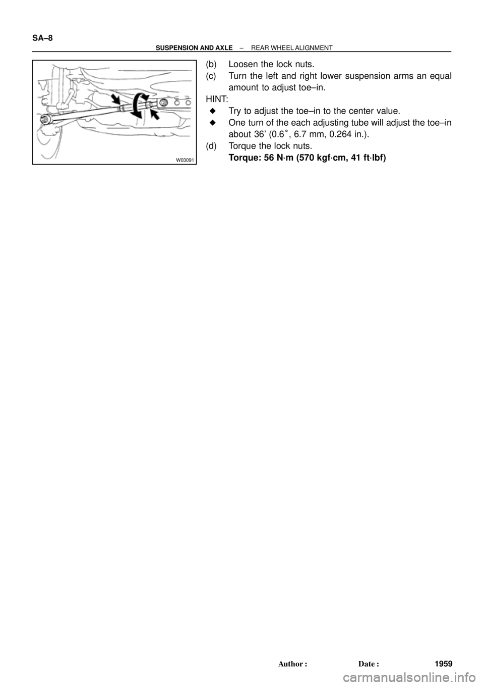
(b) Loosen the lock nuts.
(c) Turn the left and right lower suspension arms an equal
amount to adjust toe±in.
HINT:
�Try to adjust the toe±in to the center value.
�One turn of the each adjusting tube will adjust the toe±in
about 36' (0.6°, 6.7 mm, 0.264 in.).
(d) Torque the lock nuts.
Torque: 56 N´m (570 kgf´cm, 41 ft´lbf)
Page 4381 of 4770
SA07U±01
W03202
W03203
W03204
± SUSPENSION AND AXLEFRONT LOWER SUSPENSION ARM
SA±41
1992 Author�: Date�:
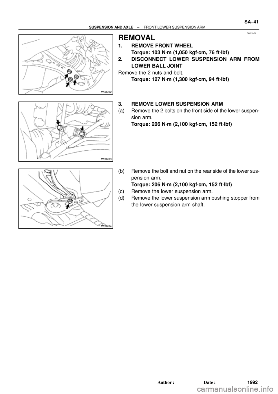
REMOVAL
1. REMOVE FRONT WHEEL
Torque: 103 N´m (1,050 kgf´cm, 76 ft´lbf)
2. DISCONNECT LOWER SUSPENSION ARM FROM
LOWER BALL JOINT
Remove the 2 nuts and bolt.
Torque: 127 N´m (1,300 kgf´cm, 94 ft´lbf)
3. REMOVE LOWER SUSPENSION ARM
(a) Remove the 2 bolts on the front side of the lower suspen-
sion arm.
Torque: 206 N´m (2,100 kgf´cm, 152 ft´lbf)
(b) Remove the bolt and nut on the rear side of the lower sus-
pension arm.
Torque: 206 N´m (2,100 kgf´cm, 152 ft´lbf)
(c) Remove the lower suspension arm.
(d) Remove the lower suspension arm bushing stopper from
the lower suspension arm shaft.
Page 4391 of 4770
SA085±01
W03210
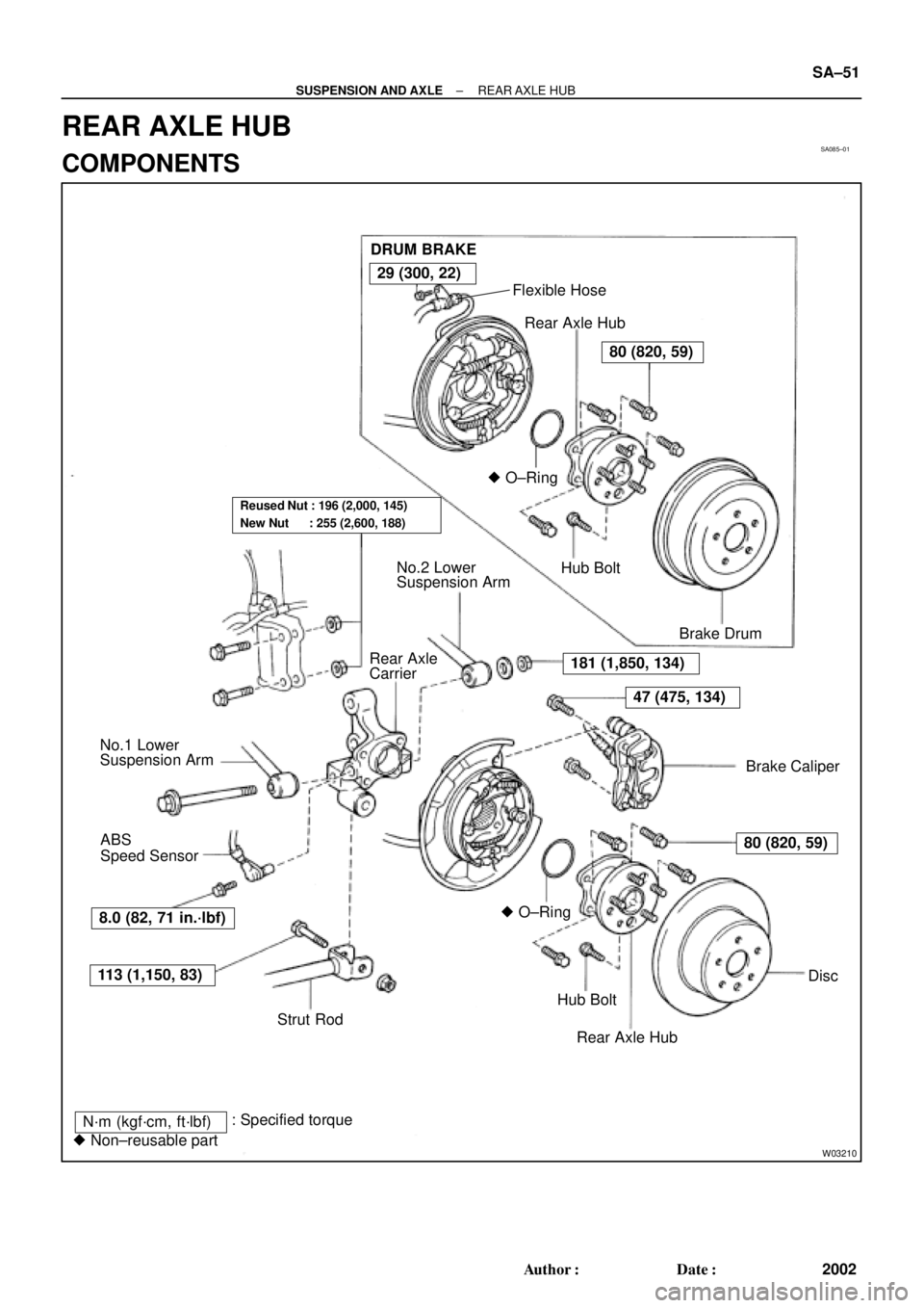
DRUM BRAKE
Flexible Hose
Rear Axle Hub
� O±Ring
Hub Bolt
Brake Drum
Brake Caliper No.2 Lower
Suspension Arm
Rear Axle
Carrier
No.1 Lower
Suspension Arm
� O±Ring
Hub Bolt
Rear Axle HubDisc ABS
Speed Sensor
Strut Rod
N´m (kgf´cm, ft´lbf)
� Non±reusable part: Specified torque
181 (1,850, 134)
47 (475, 134)
80 (820, 59)
113 (1,150, 83)
29 (300, 22)
80 (820, 59)
Reused Nut : 196 (2,000, 145)
New Nut : 255 (2,600, 188)
8.0 (82, 71 in.´lbf)
± SUSPENSION AND AXLEREAR AXLE HUB
SA±51
2002 Author�: Date�:
REAR AXLE HUB
COMPONENTS