Page 3710 of 4770

± INTRODUCTIONTERMS
IN±39
39 Author�: Date�:
OHVOverhead Valve
OPTOption
O/SOversize
P & BVProportioning And Bypass Valve
PCSPower Control System
PCVPositive Crankcase Ventilation
PKBParking Brake
PPSProgressive Power Steering
PSPower Steering
PTOPower Take±Off
R & PRack And Pinion
R/BRelay Block
RBSRecirculating Ball Type Steering
R/FReinforcement
RFSRigid Front Suspension
RRSRigid Rear Suspension
RHRight±Hand
RHDRight±Hand Drive
RLYRelay
ROMRead Only Memory
RrRear
RRRear±Engine Rear±Wheel Drive
RWDRear±Wheel Drive
SDNSedan
SENSensor
SICSStarting Injection Control System
SOCState Of Charge
SOHCSingle Overhead Camshaft
SPECSpecification
SPISingle Point Injection
SRSSupplemental Restraint System
SSMSpecial Service Materials
SSTSpecial Service Tools
STDStandard
STJCold±Start Fuel Injection
SWSwitch
SYSSystem
T/ATransaxle
TACHTachometer
TBIThrottle Body Electronic Fuel Injection
TCTurbocharger
TCCSTOYOTA Computer±Controlled System
TCVTiming Control Valve
TDCTop Dead Center
TEMP.Temperature
TEMSTOYOTA Electronic Modulated Suspension
Page 3758 of 4770

MA0676B00995
MA00O±01
N21126
N21125
MA±8
± MAINTENANCEBODY
51 Author�: Date�:
BODY
INSPECTION
1. TIGHTEN BOLTS AND NUTS ON CHASSIS AND
BODY
Tighten these parts:
�Front seat mount bolts
Torque: 37 N´m (375 kgf´cm, 27 ft´lbf)
�Front suspension member±to±body mounting bolts
Torque: 181 N´m (1,850 kgf´cm, 134 ft´lbf)
�Rear suspension member±to±body mounting nuts
Torque: 51 N´m (520 kgf´cm, 38 ft´lbf)
Check that the brakes work properly and do not drag.
2. FINAL INSPECTION
(a) Check the operation of the body parts:
�Hood:
Auxiliary catch operates properly
Hood locks securely when closed
�Front and rear doors:
Door lock operates properly
Doors close properly
�Luggage compartment door and back door:
Door lock operates properly
�Seats:
Seat adjusts easily and locks securely in any posi-
tion
Front seat back locks securely in any position
Folding±down rear seat backs lock securely
(b) Road test:
�Check the engine and chassis for abnormal noises.
�Check that the vehicle does not wander or pull to
one side.
Page 3762 of 4770

MX04C±01
Q09998
Hood
ClipCruise Control Actuator
Control Cable
Clutch Line
Bracket
Clutch Release CylinderWasher
RH Drive Shaft
Snap Ring
RH Stiffener
Plate
Ground Cable
Starter
Battery
Snap Ring
LH Drive Shaft�
RH Fender Apron
Seal
LH Stiffener Plate
Manifold StayTransaxle Back±Up Light Switch
Connector
Rear End Plate with Oil Pan
InsulatorAir Cleaner
Case Assembly
with Air Hose
Vehicle Speed Sensor
Connector
No.1 Fuel Tube Protector Engine LH
Mounting Insulator
with Bracket
Rear RH Suspension Member Brace
PS Gear Assembly
Lock Cap
Rear LH Suspension Member Brace Manifold StayClip
LH Fender Apron
Seal
Suspension Member with
Lower Suspension Arm
Front RH Suspension
Member BraceStabilizer Bar Link
Front Exhaust PipeCotter Pin
RH Fender
Liner
LH Fender Liner
Exhaust Pipe BracketNo.1 Exhaust Pipe
Support Bracket
: Specified torque
Non±reusable partGasket w/ Cruise Control:
�
�
�
Cotter Pin
�
Hole
Plug
�
�
Engine Rear Side Shutter PlateHold±Down
Clamp
Hole
Plug
12 (120, 9)
13 (130, 9)
46 (470, 34)
39 (400, 29)
6.9 (70, 61 in.´lbf)
14 (145, 10)
12 (120, 9)
39 (400, 29)
39 (400, 29)
64 (650, 47)
56 (570, 41)
37 (380, 27)
9.3 (95, 82 in.´lbf)
42 (425, 31)
32 (330, 24)
Silver Bolt: 44 (450, 33)
Green Bolt: 66 (670, 48)
62 (630, 46)
64 (650, 47)
64 (650, 47)
37 (380, 27)
181 (1,850, 134)
181 (1,850, 134)
181 (1,850, 134)
36 (370, 27)
10 (100, 7)
32 (330, 24)19 (195, 14)
49 (500, 36)
294 (3,000, 217)
Silver Bolt: 44 (450, 33)
Green Bolt: 66 (670, 48)
36 (370, 27)66 (670, 48)
39 (400, 29)
127 (1,300, 94)
33 (330, 24)
33 (330, 24)
19 (195, 14)
80 (820, 59)
Gasket�
�� �
Steering Return Pipe
Front LH
Suspension
Member Brace
N´m (kgf´cm, ft´lbf)
± MANUAL TRANSAXLE (S51)MANUAL TRANSAXLE UNIT
MX±3
1853 Author�: Date�:
MANUAL TRANSAXLE UNIT
COMPONENTS
Page 3765 of 4770
MANUAL TRANSAXLE UNIT
1856 Author�: Date�:
17. DISCONNECT PS GEAR ASSEMBLY FROM FRONT
SUSPENSION MEMBER
(a) Remove the 2 nuts and dis")
Q09989
Q09990
Q10005
Q10006
Q10007
MX±6
± MANUAL TRANSAXLE (S51)MANUAL TRANSAXLE UNIT
1856 Author�: Date�:
17. DISCONNECT PS GEAR ASSEMBLY FROM FRONT
SUSPENSION MEMBER
(a) Remove the 2 nuts and disconnect the stabilizer bar link
from the stabilizer bar.
Torque: 39 N´m (400 kgf´cm, 29 ft´lbf)
(b) Remove the 4 set bolts of the stabilizer bar bracket.
Torque: 19 N´m (195 kgf´cm, 14 ft´lbf)
(c) Remove the 2 bolts, nut and No.1 fuel tube protector.
(d) Tie the PS gear assembly to the proper position with a
code or an equivalent to suspend the assembly securely.
(e) Remove the 2 set bolts and nuts of the PS gear assembly.
Torque: 181 N´m (1,850 kgf´cm, 134 ft´lbf)
18. REMOVE 3 ENGINE FRONT SIDE MOUNTING BOLTS
Torque:
Silver bolt: 44 N´m (450 kgf´cm, 33 ft´lbf)
Green bolt: 66 N´m (670 kgf´cm, 48 ft´lbf)
19. REMOVE LH ENGINE MOUNTING INSULATOR WITH
BRACKET
(a) Remove the 2 hole plugs, nuts and 3 bolts.
Torque:
Bolt: 64 N´m (650 kgf´cm, 47 ft´lbf)
Nut: 80 N´m (820 kgf´cm, 59 ft´lbf)
(b) Lift up the transaxle and remove the left engine mounting
insulator with the bracket.
20. REMOVE HOLE PLUG AND 3 ENGINE REAR SIDE
MOUNTING NUTS
Torque: 66 N´m (670 kgf´cm, 48 ft´lbf)
21. ATTACH ENGINE SLING DEVICE TO ENGINE HANG-
ER
(See page EM±69)
22. DISCONNECT STEERING RETURN PIPE FROM
FRONT SUSPENSION MEMBER
Remove the 2 bolts.
Torque: 10 N´m (100 kgf´cm, 7 ft´lbf)
Page 3766 of 4770
MANUAL TRANSAXLE UNIT
MX±7
1857 Author�: Date�:
23. REMOVE FRONT SUSPENSION MEMBER WITH LOW-
ER SUSPENSION ARM
(a) Remove the LH and RH f")
Q10008
C
C
A
CBA
ABC A
Q10011
Q10009
± MANUAL TRANSAXLE (S51)MANUAL TRANSAXLE UNIT
MX±7
1857 Author�: Date�:
23. REMOVE FRONT SUSPENSION MEMBER WITH LOW-
ER SUSPENSION ARM
(a) Remove the LH and RH fender liner set screws.
(b) Remove the 6 bolts, 4 nuts, front LH and RH suspension
member braces, rear LH and RH suspension member
braces and front suspension member with the lower sus-
pension arm.
Torque:
Bolt A: 181 N´m (1,850 kgf´cm, 134 ft´lbf)
Bolt B: 32 N´m (330 kgf´cm, 24 ft´lbf)
Nut C: 36 N´m (370 kgf´cm, 27 ft´lbf)
24. JACK UP TRANSAXLE SLIGHTLY
Using a transmission jack, support the transaxle.
25. REMOVE LH STIFFENER PLATE
Remove the 3 bolts and LH stiffener plate.
Torque: 37 N´m (380 kgf´cm, 27 ft´lbf)
26. REMOVE REAR END PLATE WITH OIL PAN INSULA-
TOR AND RH STIFFENER PLATE
(a) Remove the 2 bolts and rear end plate with the oil pan in-
sulator.
Torque: 9.3 N´m (95 kgf´cm, 82 in.´lbf)
(b) Remove the 2 bolts and manifold stay.
Torque: 39 N´m (400 kgf´cm, 29 ft´lbf)
(c) Remove the 4 bolts and RH stiffener plate.
Torque: 39 N´m (400 kgf´cm, 29 ft´lbf)
27. REMOVE TRANSAXLE
Lower the engine left side and remove the transaxle from the
engine.
HINT:
At the time of installation, please refer to the following items.
�Align the input shaft with the clutch disc and install the
transaxle to the engine.
�Temporarily tighten the transaxle mounting bolts.
Page 3805 of 4770

w/ Cruise Control :
Cruise Control Actuator
12 (120, 9)
Clutch Line Bracket
21 (210, 15)
12 (120, 9)
Clutch Release Cylinder
26 (270, 20)
RH Drive Shaft�
�32 (330, 2")
MX04Z±01
Q09981
Hood
14 (150, 10)
w/ Cruise Control :
Cruise Control Actuator
12 (120, 9)
Clutch Line Bracket
21 (210, 15)
12 (120, 9)
Clutch Release Cylinder
26 (270, 20)
RH Drive Shaft�
�32 (330, 24)
7.8 (80, 69 in.´lbf)
Flywheel Housing Under CoverRH Fender
Apron SealClutch Accumulator
Vehicle Speed Sensor
Connector
46 (470, 34)
Engine LH Mounting
Insulator with Bracket
Rear RH Suspension Member Brace
37 (380, 27)
Transaxle
64 (650, 47)
36 (370, 27)
10 (100, 7)
Steering Return Pipe
19 (195, 14)
32 (330, 24)
181 (1,850, 134)
Silver Bolt : 44 (450, 33)
Green Bolt : 66 (670, 48)
Suspension Member with
Lower Suspension Arm
Front RH Suspension
Member Brace
181 (1,850, 134)
Control
Cable
Clip13 (130, 9)
Clip
Washer
Starter
21 (210, 15)
39 (400, 29)
Air Cleaner
Case Assembly
with Air Hose
64 (650, 47)Ground Cable
x5Back±Up Light Switch Connector
Engine Wire
20 (200, 14)Hold±Down
Clamp
Battery
LH Drive Shaft
LH Fender Apron Seal RH Exhaust Manifold Stay
64 (650, 47)
181 (1,850, 134)PS Gear Assembly
No.1 Fuel Tube Protector
49 (500, 36)
294 (3,000, 217)
Lock Cap
Rear LH Suspension Member Brace
Stabilizer Bar Link
Hole
Plug
127 (1,300, 94)
39 (400, 29)
80 (820, 59)48 (490, 35)
Silver Bolt : 44 (450, 33)
Green Bolt : 66 (670, 48)
Front LH Suspension
Member Brace RH Fender
Liner
Engine Rear Side
Shutter Plate
56 (570, 41)
�
�
62 (630, 46) �
62 (630, 46) �
Front Exhaust Pipe
No.1 Exhaust Pipe
Support Bracket
33 (330, 24)
Exhaust Pipe Support Stay
33 (330, 24)LH Fender
Liner
66 (670, 48)
Snap Ring
�Snap Ring
�Cotter Pin
�Cotter Pin
�Gasket
�Gasket
�Gasket
Non±reusable part: Specified torque
N´m (kgf´cm, ft´lbf)
�
36 (370, 27)
± MANUAL TRANSAXLE (E153)MANUAL TRANSAXLE UNIT
MX±3
1804 Author�: Date�:
MANUAL TRANSAXLE UNIT
COMPONENTS
Page 3809 of 4770
MANUAL TRANSAXLE UNIT
MX±7
1808 Author�: Date�:
21. REMOVE LH ENGINE MOUNTING INSULATOR WIT")
Q09994
Q09995
Q09996
CA
C
A
CB
AAB
C
Q09997
14 mm Head B14 mm Head B
14 mm Head A
± MANUAL TRANSAXLE (E153)MANUAL TRANSAXLE UNIT
MX±7
1808 Author�: Date�:
21. REMOVE LH ENGINE MOUNTING INSULATOR WITH
BRACKET
(a) Remove the 2 hole plugs, nuts and 3 bolts.
Torque:
Bolt: 64 N´m (650 kgf´cm, 47 ft´lbf)
Nut: 80 N´m (820 kgf´cm, 59 ft´lbf)
(b) Lift up the transaxle and remove the left engine mounting
insulator with the bracket.
22. REMOVE HOLE PLUG AND 4 ENGINE REAR SIDE
MOUNTING NUTS
Torque: 66 N´m (670 kgf´cm, 48 ft´lbf)
23. ATTACH ENGINE SLING DEVICE TO ENGINE HANG-
ER
(See page EM±69)
24. DISCONNECT STEERING RETURN PIPE FROM
FRONT SUSPENSION MEMBER
Remove the 2 bolts.
Torque: 10 N´m (100 kgf´cm, 7 ft´lbf)
25. REMOVE FRONT SUSPENSION MEMBER WITH LOW-
ER SUSPENSION ARM
(a) Remove the LH and RH fender liner set screws.
(b) Remove the 6 bolts, 4 nuts, front LH and RH suspension
member braces, rear LH and RH suspension member
braces and front suspension member with the lower sus-
pension arm.
Torque:
Bolt A: 181 N´m (1,850 kgf´cm, 134 ft´lbf)
Bolt B: 32 N´m (330 kgf´cm, 24 ft´lbf)
Nut C: 36 N´m (370 kgf´cm, 27 ft´lbf)
26. JACK UP TRANSAXLE SLIGHTLY
Using a transmission jack, support the transaxle.
27. REMOVE FLYWHEEL HOUSING UNDER COVER AND
TRANSAXLE LOWER SIDE MOUNTING BOLT
(a) Remove the 2 bolts and cover.
Torque: 7.8 N´m (80 kgf´cm, 69 in.´lbf)
(b) Remove the 3 bolts of the transaxle lower side.
Torque:
14 mm head A: 46 N´m (470 kgf´cm, 34 ft´lbf)
14 mm head B: 37 N´m (380 kgf´cm, 27 ft´lbf)
Page 3930 of 4770
PP1WM±01
± PREPARATIONSUSPENSION AND AXLE
PP±79
131 Author�: Date�:
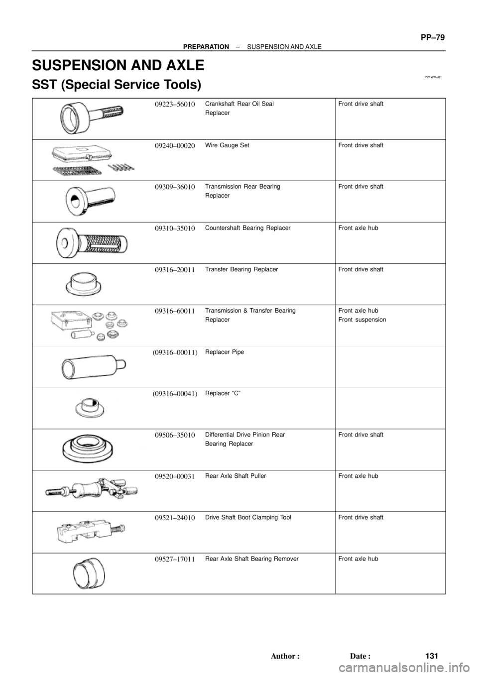
SUSPENSION AND AXLE
SST (Special Service Tools)
09223±56010Crankshaft Rear Oil Seal
ReplacerFront drive shaft
09240±00020Wire Gauge SetFront drive shaft
09309±36010Transmission Rear Bearing
ReplacerFront drive shaft
09310±35010Countershaft Bearing ReplacerFront axle hub
09316±20011Transfer Bearing ReplacerFront drive shaft
09316±60011Transmission & Transfer Bearing
ReplacerFront axle hub
Front suspension
(09316±00011)Replacer Pipe
(09316±00041)Replacer ºCº
09506±35010Differential Drive Pinion Rear
Bearing ReplacerFront drive shaft
09520±00031Rear Axle Shaft PullerFront axle hub
09521±24010Drive Shaft Boot Clamping ToolFront drive shaft
09527±17011Rear Axle Shaft Bearing RemoverFront axle hub