Page 138 of 4770
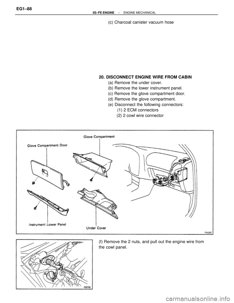
20. DISCONNECT ENGINE WIRE FROM CABIN
(a) Remove the under cover.
(b) Remove the lower instrument panel.
(c) Remove the glove compartment door.
(d) Remove the glove compartment.
(e) Disconnect the following connectors:
(1) 2 ECM connectors
(2) 2 cowl wire connector
(f) Remove the 2 nuts, and pull out the engine wire from
the cowl panel.(c) Charcoal canister vacuum hose
± 5S±FE ENGINEENGINE MECHANICALEG1±88
Page 180 of 4770
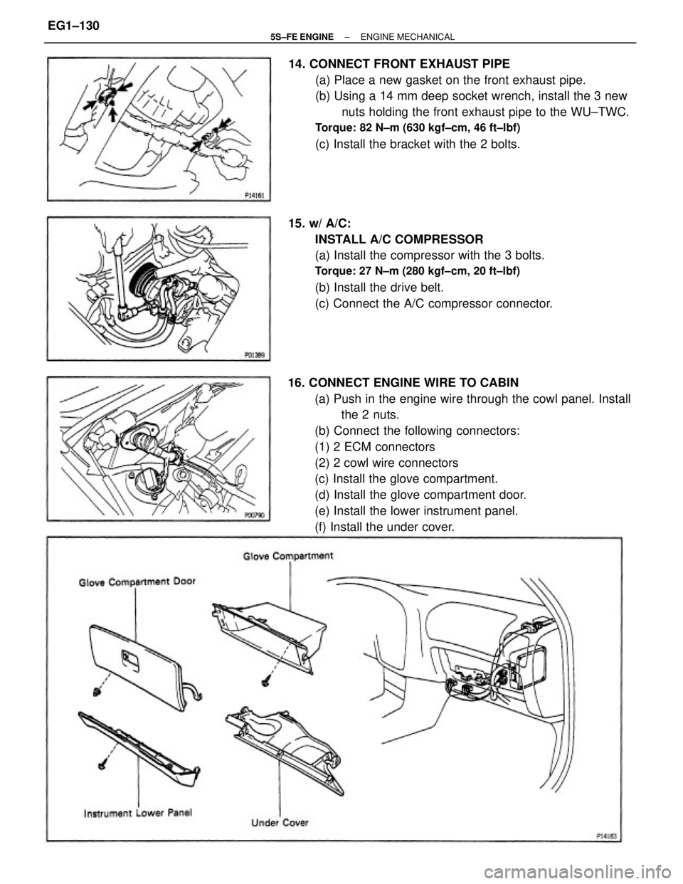
16. CONNECT ENGINE WIRE TO CABIN
(a) Push in the engine wire through the cowl panel. Install
the 2 nuts.
(b) Connect the following connectors:
(1) 2 ECM connectors
(2) 2 cowl wire connectors
(c) Install the glove compartment.
(d) Install the glove compartment door.
(e) Install the lower instrument panel.
(f) Install the under cover. 14. CONNECT FRONT EXHAUST PIPE
(a) Place a new gasket on the front exhaust pipe.
(b) Using a 14 mm deep socket wrench, install the 3 new
nuts holding the front exhaust pipe to the WU±TWC.
Torque: 82 N±m (630 kgf±cm, 46 ft±lbf)
(c) Install the bracket with the 2 bolts.
15. w/ A/C:
INSTALL A/C COMPRESSOR
(a) Install the compressor with the 3 bolts.
Torque: 27 N±m (280 kgf±cm, 20 ft±lbf)
(b) Install the drive belt.
(c) Connect the A/C compressor connector.
± 5S±FE ENGINEENGINE MECHANICALEG1±130
Page 346 of 4770
DIAGNOSIS SYSTEM
DESCRIPTION
The ECM contains a built±in self±diagnosis system by which
troubles with the engine signal network are detected and a
Malfunction indicator lamp on the instrument panel lights up.
By analyzing various signals as shown in the later table (See
page EG1±300) the Engine Control Module (ECM) detects
system malfunctions relating to the sensors or actuators.
In the normal mode, the self±diagnosis system monitors 14
items, indicated by code No. as shown in EG1±300. A mal-
function indicator lamp informs the driver that a malfunction
has been detected. The light goes off automatically when the
malfunction has been repaired. But the diagnostic trouble
code(s) remains stored in the ECM memory (except for code
Nos. 16). The ECM stores the code(s) until it is cleared by
removing the EFI fuse with the ignition switch off.
The diagnostic trouble code can be read by the number of
blinks of the malfunction indicator lamp when TE1 and E1
terminals on the data link connector 1 or 2 are connected.
When 2 or more codes are indicated, the lowest number
(code) will appear first.
In the test mode, 9 items, indicated by code No. as shown in
EG1±300 are monitored. If a malfunction is detected in any
one of the systems indicated by code Nos. 13, 22, 24, 25, 26,
27, 31, 41 and 71 the ECM lights the malfunction indicator
lamp to warn the technician that malfunction has been de-
tected. In this case, TE2 and E1 terminals on the data link
connector 1 or 2 should be connected as shown later. (See
page EG1±298).
In the test mode, even if the malfunction is corrected, the
malfunction code is stored in the ECM memory even when
the ignition switch is off (except code Nos. 43 and 51). This
also applies in the normal mode. The diagnostic mode (nor-
mal or test) and the output of the malfunction indicator lamp
can be selected by connecting the TE1, TE2 and E1 termi-
nals on the data link connector 1 or 2, as shown later.
A test mode function has been added to the functions of the
self±diagnostic system of the normal mode for the purpose of
detecting malfunctions such as poor contact, which are diffi-
cult to detect in the normal mode. This function fills up the
self±diagnosis system. The test mode can be implemented
by the technician following the appropriate procedures of
check terminal connection and operation described later.
(See page
EG1±298)
± 5S±FE ENGINEDIAGNOSIS SYSTEMEG1±296
Page 380 of 4770
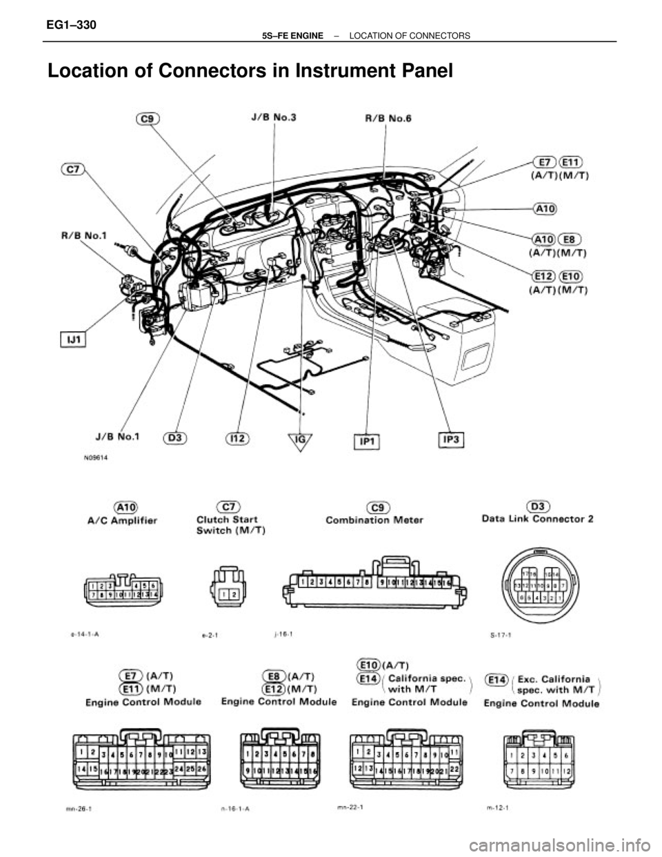
Location of Connectors in Instrument Panel
± 5S±FE ENGINELOCATION OF CONNECTORSEG1±330
Page 382 of 4770
Location of Connectors in Instrument Panel (Cont'd)
R/B No.6 R/B No.1J/B No.3 J/B No.1
± 5S±FE ENGINELOCATION OF CONNECTORSEG1±332
Page 496 of 4770
15
INTERIOR
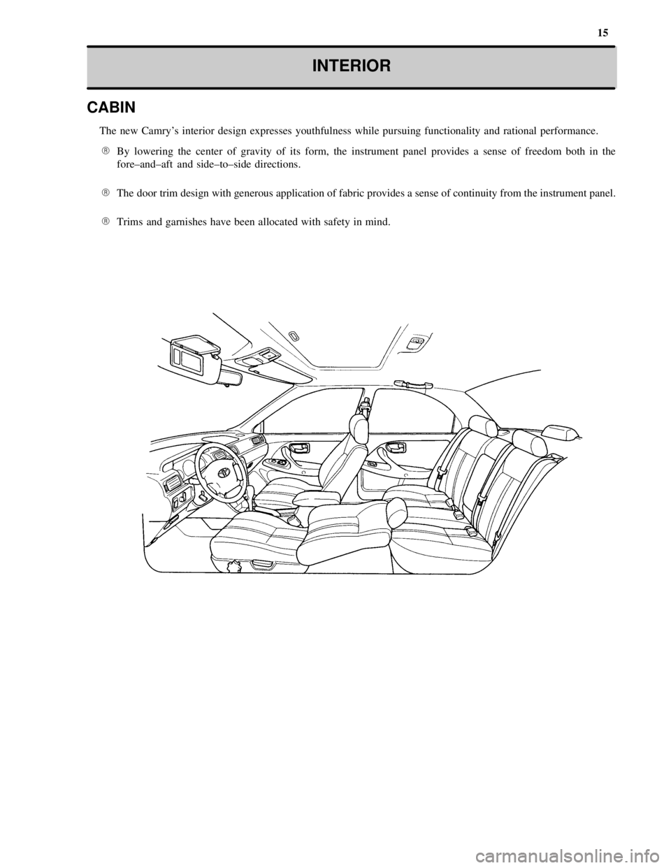
CABIN
The new Camry's interior design expresses youthfulness while pursuing functionality and rational performance.
�By lowering the center of gravity of its form, the instrument panel provides a sense of freedom both in the
fore±and±aft and side±to±side directions.
�The door trim design with generous application of fabric provides a sense of continuity from the instrument panel.
�Trims and garnishes have been allocated with safety in mind.
Page 500 of 4770
19
INTERIOR
INSTRUMENT PANEL, SWITCH LAYOUT AND EQUIPMENT
�While maintaining continuity with the door trims and the console, the instrument panel provides a form with a
lowered center of gravity to emphasize a sense of freedom.
�The unique, compact meter hood expresses a sense of sportiness.
�The frequently used audio system has been located above the heater control panel, thus improving its ease of use.
Page 505 of 4770

24
INTERIOR
� KEY REMINDER SYSTEM
All vehicles have a key reminder system as standard equipment. When the ignition key is left inserted in the ignition
key cylinder at ACC or LOCK positioon and the driver's door is opened, this system sounds a warning tone to remind
the driver to remove the ignition key.
� SRS AIRBAG
For all models, the new Camry has as standard equipment a driver's airbag in the steering wheel pad and a front
passenger airbag located in the instrument panel above the glove box.
� CRUISE CONTROL SYSTEM
The cruise control system is standard equipment on the LE and XLE grade model and an option on the CE grade
models. The main switch and control switch are on the a single lever, which is installed on the steering wheel and
can be operated easily.
� ILLUMINATED ENTRY SYSTEM
�An illuminated entry system is standard equipment on the LE and XLE models. This system makes it easy to let
the Camry in and out at night, etc.
�On the LE grade model, the ignition key cylinder illumination is turned on automatically when the door is opened.
When the door is closed, the ignition key cylinder illumination remains on for approximately 5 seconds, then goes
off automatically.
�On the XLE grade model, the illuminated entry system turns on the dome light and ignition key cylinder
illumination for approximately 15 seconds after either door is closed when passengers are entering or leaving the
vehicle. While these lights are on for 15 seconds, if the ignition switch is turned to the ACC or ON position, or if
all doors are locked, the dome light and ignition key cylinder illuminatioons go off immediately.