Page 563 of 4770
88CHASSISÐSTEERING
2. Energy Absorbing Mechanism
Construction
The energy absorbing mechanism of the steering
column consists of a lower bracket, breakaway
bracket, and energy absorbing plate.
The breakaway bracket is attached to the instrument
panel reinforcement vial the capsule and energy
absorbing plate.
The steering column and the steering gear box are
connected with an elastic intermediate shaft.
Operation
The collision is transmitted to the steering wheel, and the lower bracket and the breakaway breacket will become
detached from each other, thus moving the entire unit forward. At the same time, the energy absorbingt plate becomes
deformed to absorb the energy of the impact.
�Energy Absorbing Plate�
Page 586 of 4770

111 BODY ELECTRICALÐACCESSORIES
� SRS AIRBAG
1. General
�The SRS (Supplemental Restraint System) airbag is designed to help lessening the shock to the driver and front
passenger as a supplement to the seat belt. In a collision, the aribag sensor detects the shock and if the front±to±rear
shock is greater than a specified value, the airbags stored in the steering wheel pad for the driver and above the glove
box for the front passenger inflate instantly to help reducing the likelihood of the driver's or front passenger's head
and chest directly hitting the steering wheel or instrument panel.
�As in the '96 Avalon, a 1±sensor type airbag system is used, in chich the detection of deceleration during a collision
is accomplished by the airbag sensor enclosed in the airbag snesor assembly.
�The airbag system is controlled by the airbag sensor assembly. It has a self±diagnosis function. When it detects a
system malfunction, it lights up the SRS warning light on the combination meter to alert the driver.
The basic construction and operation are the same as in teh '96 Avalon. However, 2 types of the inflator for front
passenger have been adopted in the new Camry: TRW made and Morton made. Also, the construction of airbag sensor
assembly has been changed.
�System Diagram�
The activation processes of the SRS airbag is as illustrated below.
Page 588 of 4770

113 BODY ELECTRICALÐACCESSORIES
4. construction and Operation
Inflator and Bag for Front Passenger
1) General
The inflator and ag for front passenger are inserted inside the case, and located in the passenger side instrument panel.
the bag is made of strong nylon cloth, and becomes inflated by the argon gas flowed from the inflator. Also, 2 types
of the inflator for front passenger have been adopted: TRW made and Morton made.
2) Inflator of TRW Made
The inflator of TRW made is comprised of a squib, propellant grain, burst cup and high pressure argon gas.
If the airbag sensor is turned on by deceleration due to frontal collision, electric current then ignites the squib located
in the inflator. the frame of squib spreads instaneously to the propellant grain. If the internal pressure of the burst cup
increases by the combustion of the propellant grain, the burst cup will be released by making its bulkhead break. With
this, the gas which expanded by the tgeat of the ignition of the propellant grain flows into the airbag via the diffuser,
thus inflating the airbag.
�Construction�
Page 728 of 4770

CAMRY ± NEW FEATURES19
4. Construction and Operation
Side Airbag Sensor Assembly
1) Description
The side airbag sensor assembly is mounted on the right and left center pillars. It receives signals from
the side airbag sensor enclosed in the side airbag sensor assembly and judges whether the side airbag must
be activated or not.
2) Construction and Operation
The side airbag sensor assembly consists of side airbag sensor, safing sensor, etc.
a. Side Airbag Sensor
The side airbag sensor is enclosed in the side airbag sensor assembly based on the acceleration of the
vehicle that occurs during a side collision. The distortion created in the sensor is converted into an elec-
tric signal. This signal is a linear representation of the acceleration rate.
b. Safing Sensor
The safing sensor is enclosed in the side airbag sensor assembly. The sensor turns ON if an acceleration
force that is higher than a predetermined value is applied to the safing sensor as a result of a side colli-
sion.
Airbag Sensor Assembly
1) Description
The airbag sensor assembly is mounted on the center floor under the instrument panel.
When the airbag sensor assembly receives the airbag activation signal from the side airbag sensor assem-
bly, it applies current to the inflator.
Furthermore, the airbag sensor assembly diagnoses a system malfunction of the side airbag system.
This is the same airbag sensor assembly that is used for the
SRS airbag for the driver and front passenger.
2) Construction and Operation
The airbag sensor assembly consists of ignition control circuit, back up power source, diagnosis circuit,
memory circuit, etc.
a. Ignition Control Circuit
The ignition control circuit performs a prescribed calculation based on the signal output by the airbag
sensor and the front airbag sensor. If these calculated values are larger than a predetermined value, it
activates the ignition operation.
b. Back-Up Power Source
The back-up power source consists of a back-up capacitor and a DC-DC converter. In case of a power
system failure during a collision, the back-up capacitor discharges and supplies electric power to the
system. The DC-DC converter is a boosting transformer when the battery voltage drops below a certain
level.
c. Diagnosis Circuit
This circuit constantly diagnoses the system for any malfunction. When a malfunction is detected, it
lights up the
SRS warning light on the combination meter to alert the driver.
d. Memory Circuit
When a malfunction is detected by the diagnosis circuit, it is coded and stored in this memory circuit.
Page 767 of 4770
'99camry U
1
Part 1
OPERATION OF
INSTRUMENTS AND
CONTROLSÐ
Chapter 1±1
Overview of instruments
and controls
�Instrument panel overview
�Instrument cluster overview
�Indicator symbols on the
instrument panel
Page 768 of 4770
'99camry U
2
Instrument panel overview
1. Rear view mirror remote control levers
2. Side defroster outlets
3. Side vents
4. Instrument cluster
5. Center vents
6. Glove box
7. Electric moon roof switch and
personal light
8. Garage door opener box or
miscellaneous box
9. Power door lock switches
10. Power window switches
11. Cup holders
12. Cup holder or rear ashtray
13. Parking brake lever
14. Automatic transmission selector lever
or manual transmission gear shift lever
15. Auxiliary box
16. Hood lock release lever
Page 769 of 4770
'99camry U
3
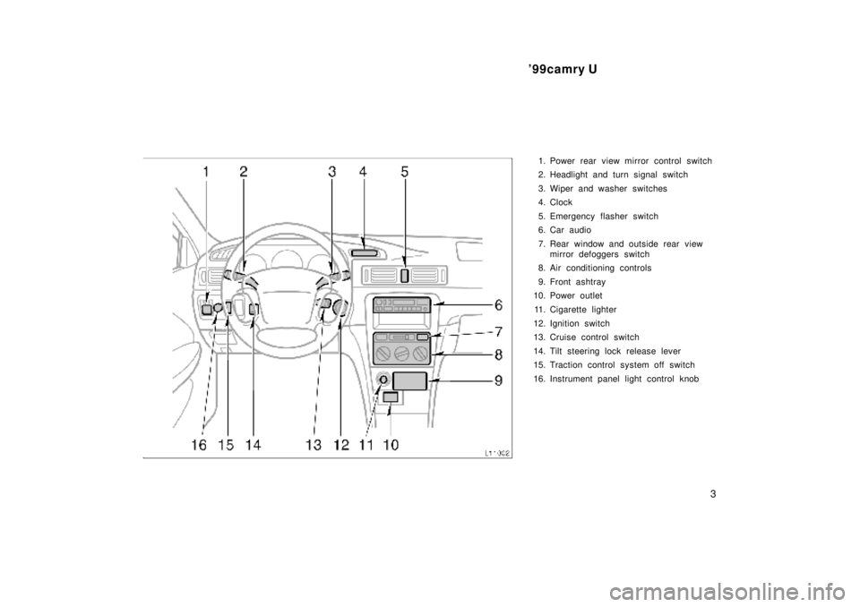
1. Power rear view mirror control switch
2. Headlight and turn signal switch
3. Wiper and washer switches
4. Clock
5. Emergency flasher switch
6. Car audio
7. Rear window and outside rear view
mirror defoggers switch
8. Air conditioning controls
9. Front ashtray
10. Power outlet
11. Cigarette lighter
12. Ignition switch
13. Cruise control switch
14. Tilt steering lock release lever
15. Traction control system off switch
16. Instrument panel light control knob
Page 771 of 4770
'99camry U
5
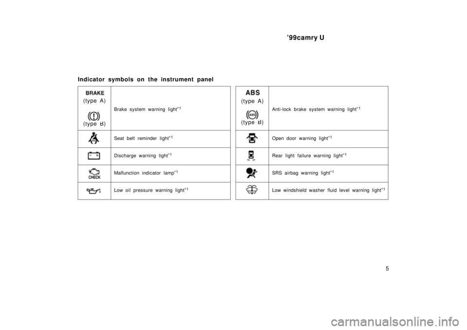
Indicator symbols on the instrument panel
Brake system warning light*
1
Seat belt reminder light*
1
Discharge warning light*
1
Malfunction indicator lamp*
1
Low oil pressure warning light*
1
Anti-lock brake system warning light*
1
(type A)
(type B)
Open door warning light*
1
Rear light failure warning light*
1
(type A)
(type B)
SRS airbag warning light*
1
Low windshield washer fluid level warning light*
1