Page 4302 of 4770
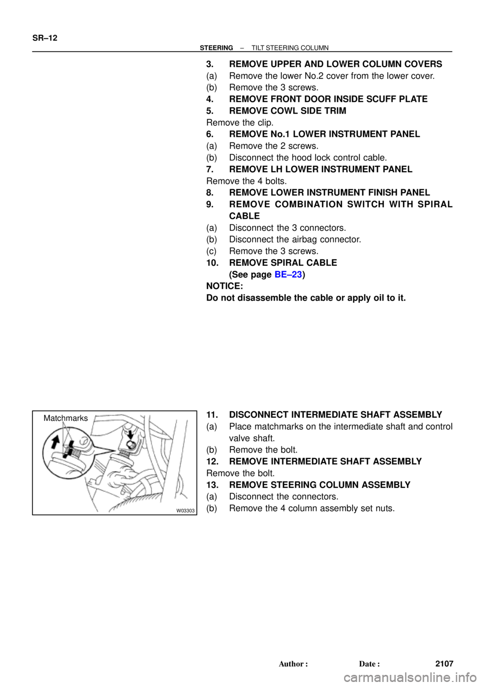
W03303
Matchmarks SR±12
± STEERINGTILT STEERING COLUMN
2107 Author�: Date�:
3. REMOVE UPPER AND LOWER COLUMN COVERS
(a) Remove the lower No.2 cover from the lower cover.
(b) Remove the 3 screws.
4. REMOVE FRONT DOOR INSIDE SCUFF PLATE
5. REMOVE COWL SIDE TRIM
Remove the clip.
6. REMOVE No.1 LOWER INSTRUMENT PANEL
(a) Remove the 2 screws.
(b) Disconnect the hood lock control cable.
7. REMOVE LH LOWER INSTRUMENT PANEL
Remove the 4 bolts.
8. REMOVE LOWER INSTRUMENT FINISH PANEL
9. REMOVE COMBINATION SWITCH WITH SPIRAL
CABLE
(a) Disconnect the 3 connectors.
(b) Disconnect the airbag connector.
(c) Remove the 3 screws.
10. REMOVE SPIRAL CABLE
(See page BE±23)
NOTICE:
Do not disassemble the cable or apply oil to it.
11. DISCONNECT INTERMEDIATE SHAFT ASSEMBLY
(a) Place matchmarks on the intermediate shaft and control
valve shaft.
(b) Remove the bolt.
12. REMOVE INTERMEDIATE SHAFT ASSEMBLY
Remove the bolt.
13. REMOVE STEERING COLUMN ASSEMBLY
(a) Disconnect the connectors.
(b) Remove the 4 column assembly set nuts.
Page 4306 of 4770
SR06M±01
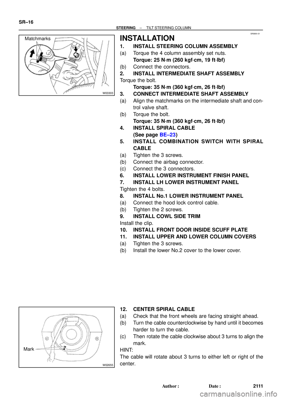
W03303
Matchmarks
W02655
Mark SR±16
± STEERINGTILT STEERING COLUMN
2111 Author�: Date�:
INSTALLATION
1. INSTALL STEERING COLUMN ASSEMBLY
(a) Torque the 4 column assembly set nuts.
Torque: 25 N´m (260 kgf´cm, 19 ft´lbf)
(b) Connect the connectors.
2. INSTALL INTERMEDIATE SHAFT ASSEMBLY
Torque the bolt.
Torque: 35 N´m (360 kgf´cm, 26 ft´lbf)
3. CONNECT INTERMEDIATE SHAFT ASSEMBLY
(a) Align the matchmarks on the intermediate shaft and con-
trol valve shaft.
(b) Torque the bolt.
Torque: 35 N´m (360 kgf´cm, 26 ft´lbf)
4. INSTALL SPIRAL CABLE
(See page BE±23)
5. INSTALL COMBINATION SWITCH WITH SPIRAL
CABLE
(a) Tighten the 3 screws.
(b) Connect the airbag connector.
(c) Connect the 3 connectors.
6. INSTALL LOWER INSTRUMENT FINISH PANEL
7. INSTALL LH LOWER INSTRUMENT PANEL
Tighten the 4 bolts.
8. INSTALL No.1 LOWER INSTRUMENT PANEL
(a) Connect the hood lock control cable.
(b) Tighten the 2 screws.
9. INSTALL COWL SIDE TRIM
Install the clip.
10. INSTALL FRONT DOOR INSIDE SCUFF PLATE
11. INSTALL UPPER AND LOWER COLUMN COVERS
(a) Tighten the 3 screws.
(b) Install the lower No.2 cover to the lower cover.
12. CENTER SPIRAL CABLE
(a) Check that the front wheels are facing straight ahead.
(b) Turn the cable counterclockwise by hand until it becomes
harder to turn the cable.
(c) Then rotate the cable clockwise about 3 turns to align the
mark.
HINT:
The cable will rotate about 3 turns to either left or right of the
center.
Page 4414 of 4770

W03303
Matchmarks SR±12
± STEERINGTILT STEERING COLUMN
2097 Author�: Date�:
2001 CAMRY (RM819U)
3. REMOVE UPPER AND LOWER COLUMN COVERS
(a) Remove the lower No.2 cover from the lower cover.
(b) Remove the 3 screws, upper and lower column covers.
4. REMOVE FRONT DOOR INSIDE SCUFF PLATE
5. REMOVE COWL SIDE TRIM
Remove the clip and cowl side trim.
6. REMOVE No.1 LOWER INSTRUMENT PANEL
(a) Remove the 2 screws.
(b) Disconnect the hood lock control cable.
(c) Remove the No.1 lower instrument panel.
7. REMOVE LH LOWER INSTRUMENT PANEL
Remove the 4 bolts and LH lower instrument panel.
8. REMOVE LOWER INSTRUMENT FINISH PANEL
9. REMOVE COMBINATION SWITCH WITH SPIRAL
CABLE
(a) Disconnect the 3 connectors.
(b) Disconnect the airbag connector.
(c) Remove the 3 screws and combination switch with spiral
cable.
10. REMOVE SPIRAL CABLE (See page BE±23)
NOTICE:
Do not disassemble the cable or apply oil to it.
11. DISCONNECT INTERMEDIATE SHAFT ASSEMBLY
(a) Place matchmarks on the intermediate shaft and control
valve shaft.
(b) Remove the bolt and disconnect the intermediate shaft
assembly.
12. REMOVE INTERMEDIATE SHAFT ASSEMBLY
Remove the bolt and intermediate shaft assembly.
13. REMOVE STEERING COLUMN ASSEMBLY
(a) Disconnect the connectors.
(b) Remove the 4 column assembly set nuts and steering col-
umn assembly.
Page 4423 of 4770
Toyota Supports ASE CertificationPage 1 of 2
AX003±00Title:
PORT INSTALLED RS3000 TVIP TRUNK
COURTESY CONNECTION
Models:
'99 Camry
Technical Service
BULLETIN
March 31, 2000
The trunk courtesy connection for 1999 model year Camry vehicles equipped with a Port
Installed Option RS3000 (V3) has been relocated from the luggage compartment light
switch to below the dash (lower finish panel) on the driver's side in the Instrument Panel
J/B. (Refer to Illustrations A & B on page 2.)
The location was changed to improve the installation process.
A splicing connector is used for the new trunk courtesy wire installation (blue) to the
vehicle's wire harness at Instrument Panel J/B (red/yellow).
The previous location is the same as the dealer installed RS3000 trunk courtesy
connection to the luggage compartment light switch connection.
For service related purposes, this bulletin describes the procedures to locate the new
trunk courtesy connection at Instrument Panel J/B in vehicles equipped with PIO
RS3000.
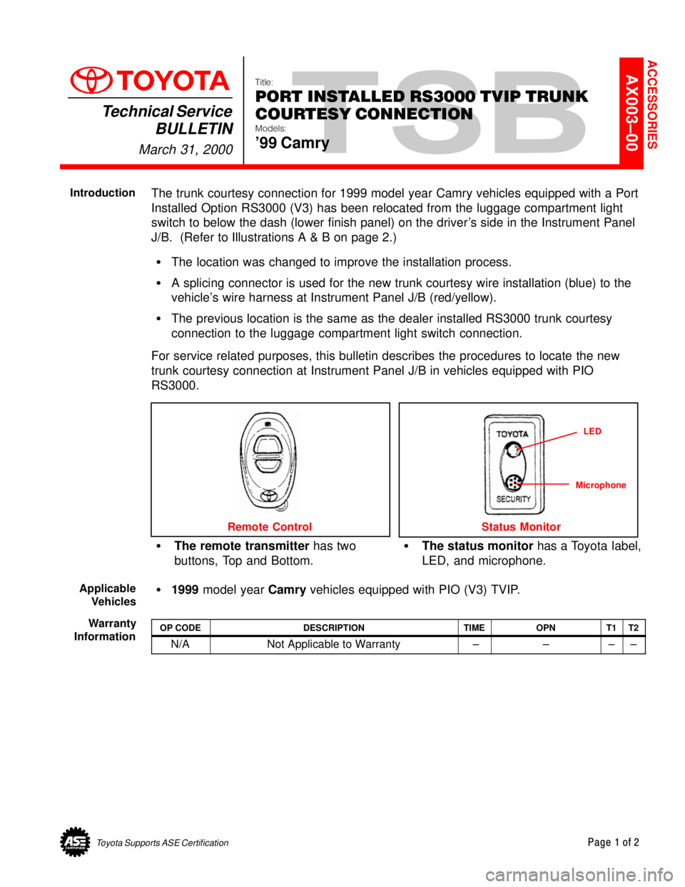
The remote transmitter has two
buttons, Top and Bottom.The status monitor has a Toyota label,
LED, and microphone.
Remote Control
LED
Status Monitor
Microphone
1999 model year Camry vehicles equipped with PIO (V3) TVIP.
OP CODEDESCRIPTIONTIMEOPNT1T2
N/ANot Applicable to Warranty ±±±±
ACCESSORIES
Introduction
Applicable
Vehicles
Warranty
Information
Page 4517 of 4770
TOYOTA MOTOR SALES U.S.A., INC.
This TSB outlines the causes of brake vibration and pulsation, as well as the best corrective
measures to use.
CONTENTS
1) Symptoms of brake vibration and pulsation
2) Cause of vibration/pulsation problems
3) Advantages of using an on±car brake lathe
4) Rotor replacement and off±car brake lathe procedure
1) SYMPTOMS OF BRAKE VIBRATION AND PULSATION
Brake vibration problems generally involve one or both of two phenomena: body vibration and/
or pedal pulsation.
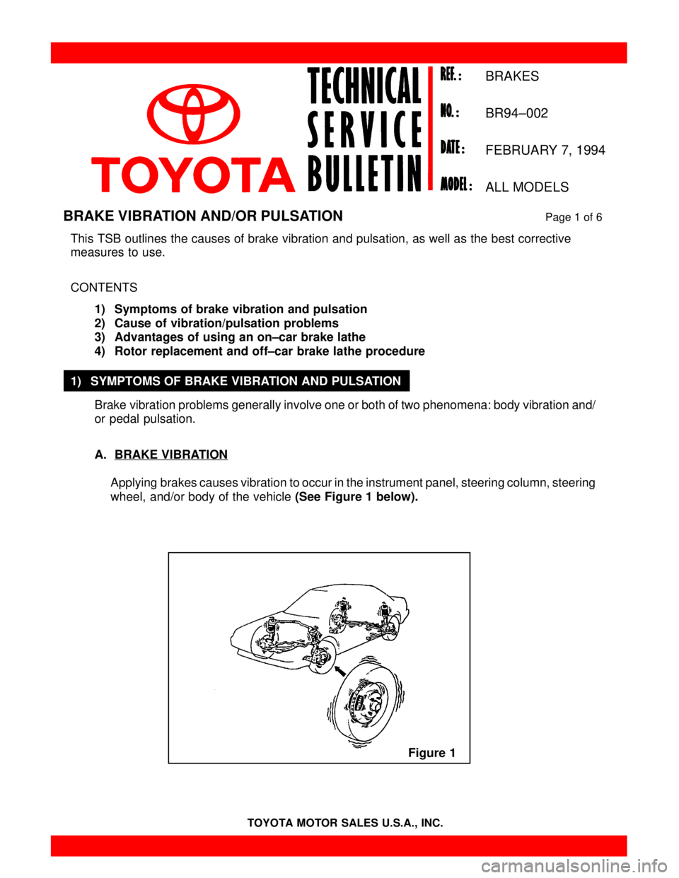
A. BRAKE VIBRATION
Applying brakes causes vibration to occur in the instrument panel, steering column, steering
wheel, and/or body of the vehicle (See Figure 1 below).
BRAKE VIBRATION AND/OR PULSATIONPage 1 of 6
BRAKES
BR94±002
FEBRUARY 7, 1994
ALL MODELS
Figure 1
Page 4590 of 4770
POOR HEATER PERFORMANCE ± EL007±00 April 14, 2000
Page 3 of 4
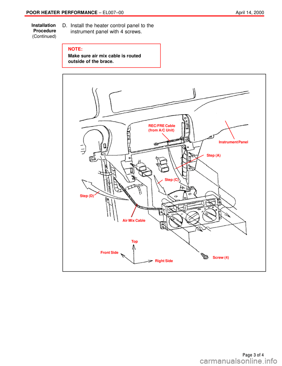
D. Install the heater control panel to the
instrument panel with 4 screws.
NOTE:
Make sure air mix cable is routed
outside of the brace.
REC/FRE Cable
(from A/C Unit)
Step (C)Instrument Panel
Step (A)
Step (D)
Air Mix Cable
Screw (4)
Right Side Front SideTo p
Installation
Procedure
(Continued)
Page 4645 of 4770

WARRANTY PARTS MARKING PROCEDURE ± PG006-03September 26, 2003
Page 2 of 3
Dealers are requested to mark the location of the failure of all warranty parts that are
listed below.
This list is not inclusive. There may be other components that can be
marked in the area of failure. All other parts that can be marked should be marked.
assist grip assy headlamps
audio (blemish) headliner
back door garnish hoses
bumper covers instrument panel safety pad sub±assy
cargo cover (retractable) Interior light assemblies and covers
carpet knobs, levers, handles
clutch disc l/pulley pump assy
clutch flywheel mirrors (side and rearview)
combination meter glass navigation or VES screens
console and components pillar garnish
cowl assy rack and pinion/power steering gear assy
cowl side trim sub±assy radiator
cupholders room partition board
cylinder head cover sub±assy rotors (mark where min. runout is exceeded or warped)
dash panel insulator assy seat covers/cushions
dashboard and trim seat tracks
disc wheel soft trim
display panels spare tire cover
door handle assy steering column cover
door moulding steering wheel
door trim panel & molding tail lamps and covers
emblems transmission oil pan
engine oil pan visor
exhaust manifold washer jar
floor and cargo mats wheel cap
gear shift knob wheels
grills
Parts
Marking
Requirement
Parts
Marking
List