Page 30 of 4770

CAMRY ± NEW FEATURES
No.4 INJECTOR
SPARK PLUGSIGNITERS and
IGNITION COILS
No.2 INJECTOR
No.1 INJECTOR
No.3 INJECTOR
SENSORS ACTUATORS
MANIFOLD ABSOLUTE
PRESSURE SENSORSFI PIM#10+
CRANKSHAFT POSITION
SENSORNE
CAMSHAFT POSITION
SENSORG
ENGINE COOLANT TEMP.
SENSORTHW
INTAKE AIR TEMP. SENSORTHA
THROTTLE POSITION SENSORVTA
COMBINATION METER
SPD
�Vehicle Speed Signal
AIR FUEL RATIO SENSOR
(Bank 1, Sensor 1)AF
HEATED OXYGEN SENSOR
(Bank 1, Sensor 2)OX2
POWER STEERING OIL
PRESSER SWITCHPSW
TAILLIGHT & REAR WINDOW
DEFOGGER SYSTEMELS
IGNITION SWITCHSTA
PARK / NEUTRAL POSITION
SWITCHNSW
STOP LIGHT SWITCHSTP
AIRBAG SENSOR ASSEMBLY
F/PS
�Fuel Cut-Off Signal
#10
#20+
#20
#30+
#30
#40+
#40
ESA
IGT1,
IGT2
IGF
CONTROL VALVEIACRSD
VSV EGREGR
AIR FUEL RATIO SENSOR
HEATER AIR FUEL RATIO SENSOR
HEATER CONTROLHTAF
HEATED OXYGEN SENSOR
HEATER OXYGEN SENSOR HEATER
CONTROLHT2
MAGNET CLUTCH RERAYAIRE CONDITIONING
CUT-OFF CONTROLMGC
FUEL GAGE
LOW FUEL LEVEL WARNING
LIGHT
ECM
AIR CONDITIONING SWITCHA/C SW
R, 2, L
FUEL
FUEL W
50
Construction
The configuration of the engine control system in the 5S-FNE engine is as shown in the following chart.
(Continued)
Page 68 of 4770
2. CONNECT TACHOMETER AND TIMING LIGHT TO
ENGINE
Connect the test probe of a tachometer to terminal IG
(±) of the data link connector 1.
NOTICE:
wNEVER allow the tachometer terminal to touch
ground as it could result in damage to the igniter
and/or ignition coif.
wAs some tachometers are not compatible with this
Ignition system, we recommend that you confirm
the compatibility of yours before use.
3. ADJUST IGNITION TIMING
(a) Using SST, connect terminals TE1 and E1 of the data
link connector 1.
SST 09843±18020
HINT: After engine speed is kept at 1,000 ± 1,300
rpm for 5 seconds, check that it returns to idle speed.
IGNITION TIMING INSPECTION AND
ADJUSTMENT
1. WARM UP ENGINE
Allow the engine to warm up to normal operating
temperature.
(b) Using a timing light, check the ignition timing.
Ignition timing:
10
� BTDC @ idle
(Transmission in neutral position)
± 5S±FE ENGINEENGINE MECHANICALEG1±18
Page 70 of 4770
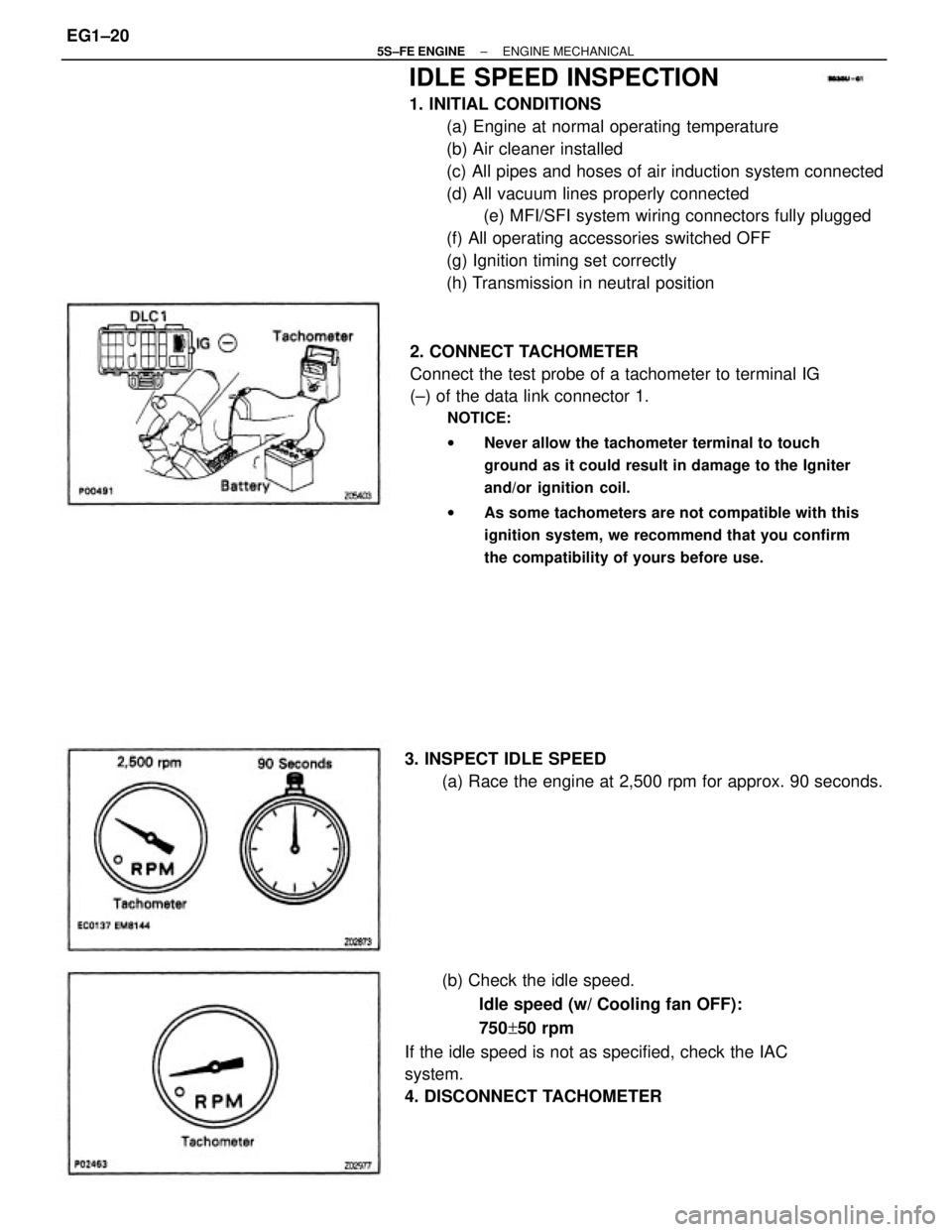
IDLE SPEED INSPECTION
1. INITIAL CONDITIONS
(a) Engine at normal operating temperature
(b) Air cleaner installed
(c) All pipes and hoses of air induction system connected
(d) All vacuum lines properly connected
(e) MFI/SFI system wiring connectors fully plugged
(f) All operating accessories switched OFF
(g) Ignition timing set correctly
(h) Transmission in neutral position
2. CONNECT TACHOMETER
Connect the test probe of a tachometer to terminal IG
(±) of the data link connector 1.
NOTICE:
wNever allow the tachometer terminal to touch
ground as it could result in damage to the Igniter
and/or ignition coil.
wAs some tachometers are not compatible with this
ignition system, we recommend that you confirm
the compatibility of yours before use.
(b) Check the idle speed.
Idle speed (w/ Cooling fan OFF):
750+50 rpm
If the idle speed is not as specified, check the IAC
system.
4. DISCONNECT TACHOMETER 3. INSPECT IDLE SPEED
(a) Race the engine at 2,500 rpm for approx. 90 seconds.
± 5S±FE ENGINEENGINE MECHANICALEG1±20
Page 136 of 4770
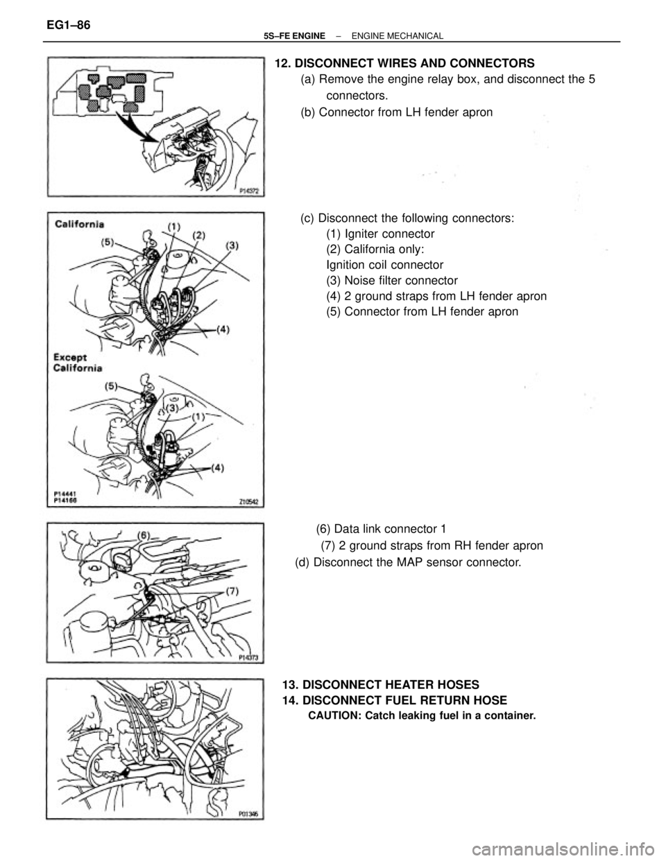
(c) Disconnect the following connectors:
(1) Igniter connector
(2) California only:
Ignition coil connector
(3) Noise filter connector
(4) 2 ground straps from LH fender apron
(5) Connector from LH fender apron 12. DISCONNECT WIRES AND CONNECTORS
(a) Remove the engine relay box, and disconnect the 5
connectors.
(b) Connector from LH fender apron
(6) Data link connector 1
(7) 2 ground straps from RH fender apron
(d) Disconnect the MAP sensor connector.
13. DISCONNECT HEATER HOSES
14. DISCONNECT FUEL RETURN HOSE
CAUTION: Catch leaking fuel in a container.
± 5S±FE ENGINEENGINE MECHANICALEG1±86
Page 182 of 4770
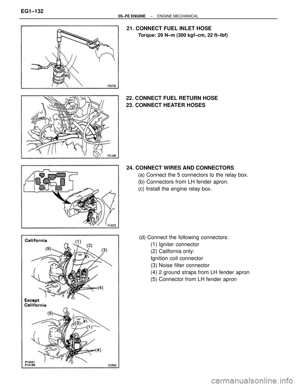
(d) Connect the following connectors:
(1) Igniter connector
(2) California only:
Ignition coil connector
(3) Noise filter connector
(4) 2 ground straps from LH fender apron
(5) Connector from LH fender apron 24. CONNECT WIRES AND CONNECTORS
(a) Connect the 5 connectors to the relay box.
(b) Connectors from LH fender apron.
(c) Install the engine relay box. 21. CONNECT FUEL INLET HOSE
Torque: 29 N±m (300 kgf±cm, 22 ft±lbf)
22. CONNECT FUEL RETURN HOSE
23. CONNECT HEATER HOSES
± 5S±FE ENGINEENGINE MECHANICALEG1±132
Page 285 of 4770
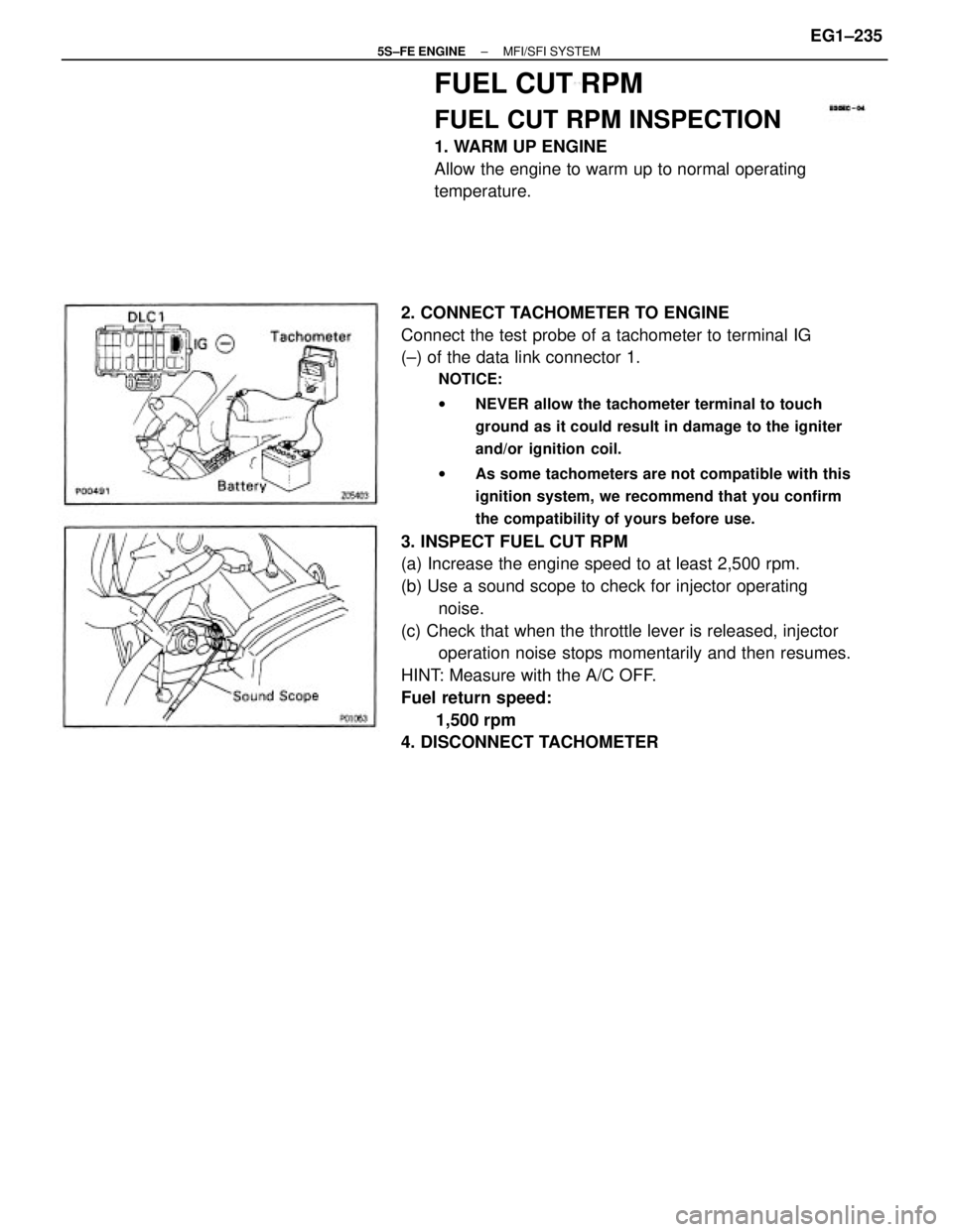
2. CONNECT TACHOMETER TO ENGINE
Connect the test probe of a tachometer to terminal IG
(±) of the data link connector 1.
NOTICE:
wNEVER allow the tachometer terminal to touch
ground as it could result in damage to the igniter
and/or ignition coil.
wAs some tachometers are not compatible with this
ignition system, we recommend that you confirm
the compatibility of yours before use.
3. INSPECT FUEL CUT RPM
(a) Increase the engine speed to at least 2,500 rpm.
(b) Use a sound scope to check for injector operating
noise.
(c) Check that when the throttle lever is released, injector
operation noise stops momentarily and then resumes.
HINT: Measure with the A/C OFF.
Fuel return speed:
1,500 rpm
4. DISCONNECT TACHOMETER
FUEL CUT RPM
FUEL CUT RPM INSPECTION
1. WARM UP ENGINE
Allow the engine to warm up to normal operating
temperature.
± 5S±FE ENGINEMFI/SFI SYSTEMEG1±235
Page 351 of 4770
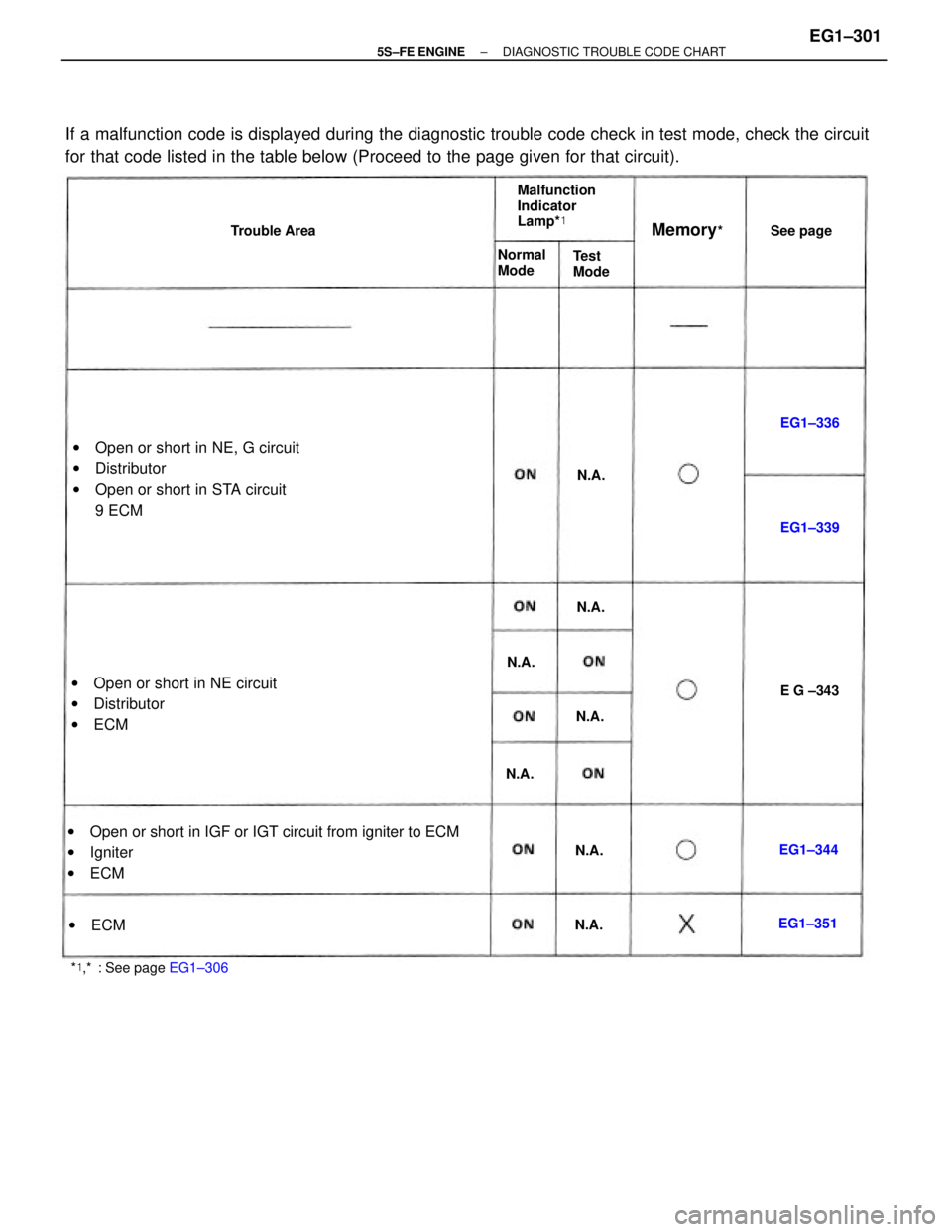
If a malfunction code is displayed during the diagnostic trouble code check in test mode, check the circuit
for that code listed in the table below (Proceed to the page given for that circuit).
wOpen or short in IGF or IGT circuit from igniter to ECM
wIgniter
wECM wOpen or short in NE, G circuit
wDistributor
wOpen or short in STA circuit
9 ECM
wOpen or short in NE circuit
wDistributor
wECM
Malfunction
Indicator
Lamp*�
*�,*�: See page EG1±306Normal
Mode Trouble Area
Memory*�
Test
ModeSee page
EG1±351EG1±339
wECM
E G ±343 EG1±336
EG1±344 N.A.
N.A.N.A.
N.A. N.A.
N.A.N.A.
± 5S±FE ENGINEDIAGNOSTIC TROUBLE CODE CHARTEG1±301
Page 361 of 4770
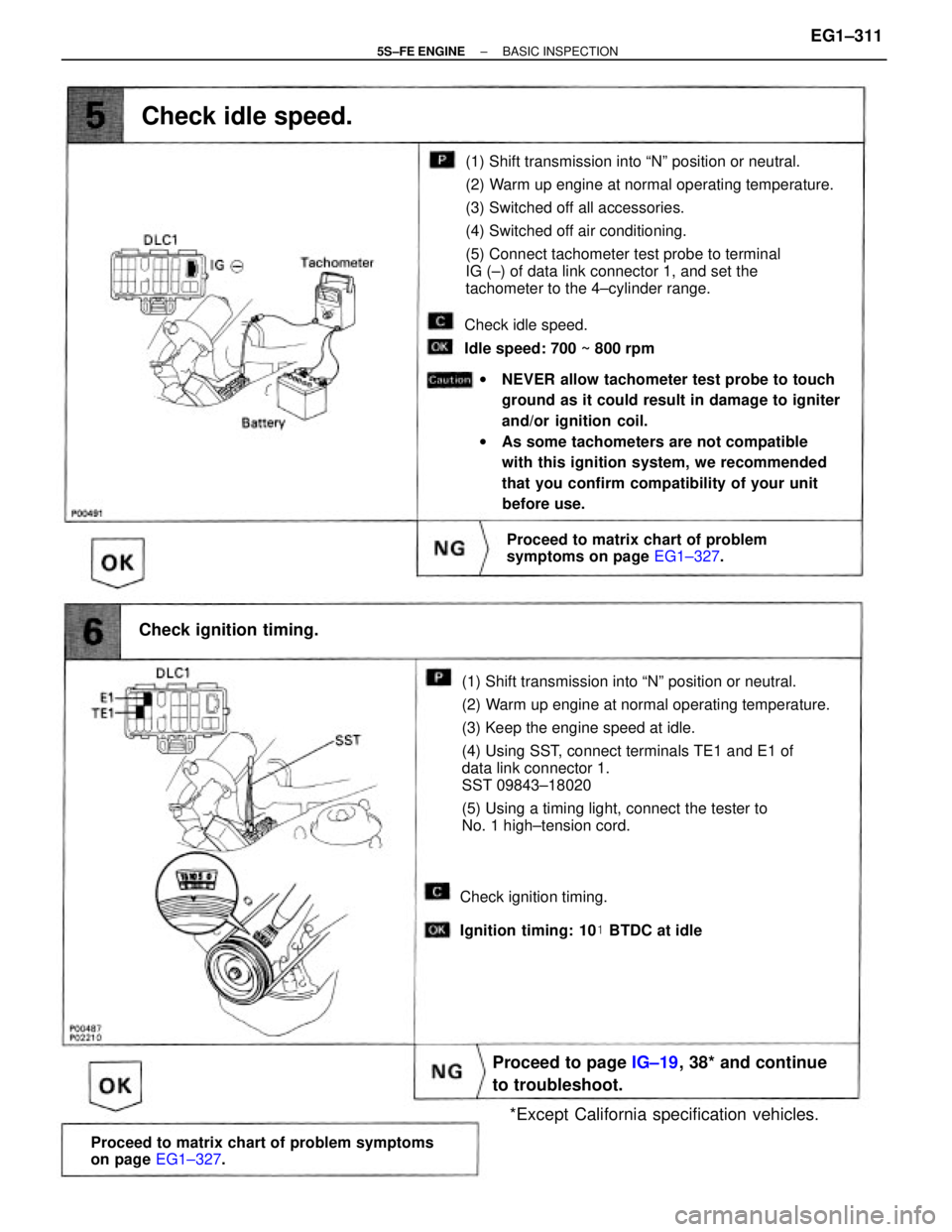
(1) Shift transmission into ªNº position or neutral.
(2) Warm up engine at normal operating temperature.
(3) Keep the engine speed at idle.
(4) Using SST, connect terminals TE1 and E1 of
data link connector 1.
SST 09843±18020
(5) Using a timing light, connect the tester to
No. 1 high±tension cord.(1) Shift transmission into ªNº position or neutral.
(2) Warm up engine at normal operating temperature.
(3) Switched off all accessories.
(4) Switched off air conditioning.
(5) Connect tachometer test probe to terminal
IG (±) of data link connector 1, and set the
tachometer to the 4±cylinder range.
wNEVER allow tachometer test probe to touch
ground as it could result in damage to igniter
and/or ignition coil.
wAs some tachometers are not compatible
with this ignition system, we recommended
that you confirm compatibility of your unit
before use.
Proceed to matrix chart of problem symptoms
on page EG1±327.
Proceed to page IG±19, 38* and continue
to troubleshoot.
Proceed to matrix chart of problem
symptoms on page EG1±327.
*Except California specification vehicles. Check ignition timing.
Check idle speed.
Check idle speed.
Idle speed: 700 ~ 800 rpm
Check ignition timing.
Ignition timing: 10� BTDC at idle
± 5S±FE ENGINEBASIC INSPECTIONEG1±311