Page 181 of 447
AUTOMATIC TRANSMISSION (4 A/T) 7B-139
REQUIRED SERVICE MATERIAL
NOTE:
This kit includes the following items.
1. Storage case, 2. Operator’s manual, 3. SUZUKI scan tool (Tech-1A), 4. DLC cable,
5. Test lead / probe, 6. Power source cable, 7. DLC cable adaptor, 8. Self-test adaptor
MaterialRecommended SUZUKI product
(Part Number)Use
Automatic transmission fluid
An equivalent of DEXRON
®-III or
DEXRONR
®-IIEAutomatic transmission
Parts lubrication when installing
Sealant SUZUKI BOND No. 1215
(99000-31110)Case housing star-shaped recess
bolts
(3 pcs only)
Lithium grease SUZUKI SUPER GREASE C
(99000-25030)Retaining parts in place when
assembling
Oil seal lips
D-rings
O-rings
SUZUKI SUPER GREASE A
(99000-25010)Cable ends
Converter center cup
Thread lock cement THREAD LOCK 1322
(99000-32110)Final gear bolts
Torque converter housing bolts
Page 183 of 447

CLUTCH 7C-1
6F1
6F2
6G
6H
6K
7A1
7B1
7C1
7D
7E
7C
8A
8B
8C
8D
8E
9
10
10A
10B
SECTION 7C
CLUTCH
CONTENTS
GENERAL DESCRIPTION .............................. 7C-2
DIAGNOSIS ..................................................... 7C-3
ON-VEHICLE SERVICE .................................. 7C-4
CLUTCH CABLE .......................................... 7C-4
CLUTCH PEDAL AND CLUTCH PEDAL
BRACKET .................................................... 7C-6
CLUTCH PEDAL HEIGHT ....................... 7C-7
CLUTCH PEDAL FREE TRAVEL ............ 7C-7UNIT REPAIR OVERHAUL ............................. 7C-8
CLUTCH COVER, CLUTCH DISC AND
FLYWHEEL.................................................. 7C-8
CLUTCH RELEASE SYSTEM ................... 7C-11
TIGHTENING TORQUE SPECIFICATION.... 7C-14
REQUIRED SERVICE MATERIAL................ 7C-14
SPECIAL TOOL ............................................ 7C-14
WARNING:
For vehicles equipped with Supplemental Restraint (Air Bag) System:
Service on and around the air bag system components or wiring must be performed only by an
authorized SUZUKI dealer. Refer to “Air Bag System Components and Wiring Location View” under
“General Description” in air bag system section in order to confirm whether you are performing ser-
vice on or near the air bag system components or wiring. Please observe all WARNINGS and “Ser-
vice Precautions” under “On-Vehicle Service” in air bag system section before performing service
on or around the air bag system components or wiring. Failure to follow WARNINGS could result in
unintentional activation of the system or could render the system inoperative. Either of these two
conditions may result in severe injury.
Technical service work must be started at least 90 seconds after the ignition switch is turned to the
“LOCK” position and the negative cable is disconnected from the battery. Otherwise, the system
may be activated by reserve energy in the Sensing and Diagnostic Module (SDM).
Page 186 of 447
7C-4 CLUTCH
ON-VEHICLE SERVICE
CLUTCH CABLE
REMOVAL
1) Disconnect negative cable at battery.
2) Remove clutch cable joint nut (1).
3) Remove joint pin (2) from clutch release lever (3).
4) Disconnect cable hook (1) from clutch pedal (4).
5) Remove clutch cable (3) from bracket (5) by turning cable
cap (2) about 90° as shown.
1. Clutch cable 6. Pedal bracket
2. Release lever 7. Adjusting bolt
3. Joint pin
: Apply grease 99000-25010 to joint pin.8. Lock nut
4. Joint nut 9. Clutch cable hook
: Apply grease 99000-25010 to cable hook.
5. Clutch pedal Tightening torque
Page 188 of 447
7C-6 CLUTCH
CLUTCH PEDAL AND CLUTCH PEDAL BRACKET
1. Clutch cable hook
: Apply grease 99000-25010 to cable
hook.7. Pedal spring
: Apply grease 99000-25010 to inside surface
of spring.13. Adjusting bolt cap
2. Clutch pedal bracket 8. Pedal shaft spacer
: Apply grease 99000-25010 to outside sur-
face of spacer.14. Adjusting bolt
3. Bolt 9. Pedal shaft 15. Lock nut
4.
Nut10.
Clutch pedalTightening torque
5. Pedal shaft nut 11. Pedal pad
6. Pedal bush 12. Pedal return cushion
Page 227 of 447

REAR DIFFERENTIAL 7F-5
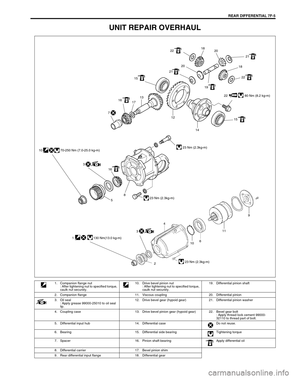
UNIT REPAIR OVERHAUL
22 80 Nm (8.2 kg-m) 1513
17 16
15 12
14 7
22
22 2121
2020
1918 18
16 3 10 70-250 Nm (7.0-25.0 kg-m)
23 Nm (2.3kg-m)
23 Nm (2.3kg-m)
8
5
10
2611
23 Nm (2.3kg-m)
9
4
1 130 Nm(13.0 kg-m)
3
1. Companion flange nut
: After tightening nut to specified torque,
caulk nut securely.10. Drive bevel pinion nut
: After tightening nut to specified torque,
caulk nut securely.19. Differential pinion shaft
2. Companion flange 11. Viscous coupling 20. Differential pinion
3. Oil seal
: Apply grease 99000-25010 to oil seal
lip.12. Drive bevel gear (hypoid gear) 21. Differential pinion washer
4. Coupling case 13. Drive bevel pinion gear (hypoid gear) 22. Bevel gear bolt
: Apply thread lock cement 99000-
32110 to thread part of bolt.
5. Differential input hub 14. Differential case Do not reuse.
6. Bearing 15. Differential side bearing Tightening torque
7. Spacer 16. Pinion shaft bearing Apply differential oil
8. Differential carrier 17. Bevel pinion shim
9. Rear differential input flange 18. Differential gear
Page 235 of 447
REAR DIFFERENTIAL 7F-13
2) If thrust play is out of specification, select suitable side
washer from among following available size, install it and
check again that specified gear play is obtained.
Available side washer thickness
0.90, 1.00 and 1.10 mm (0.035, 0.039 and 0.043 in.)
3) Put drive bevel gear (1) on differential case (2) and fasten
them with bolts (3) by tightening them to specified torque.
Use thread lock cement for bolts (3).
“A” : Thread lock cement 99000-32110
Tightening torque
Drive bevel gear bolts (a) : 80 N·m (8.0 kg-m, 58.0 lb-ft)
4) Press-fit differential side bearings (3) to differential case (1)
by using special tools.
Special tool
(A) : 09951-76010
(B) : 09951-16060 CAUTION:
Use of any other bolts than that specified is prohibited.
2
1 3, “A”, (a)
2. Drive bevel gear
Page 238 of 447

7F-16 REAR DIFFERENTIAL
8) Place zero-adjusted mounting dummy (1) and dial gauge set
on pinion dummy (2) and take measurement between zero
position and extended dial gauge measuring tip.
9) Obtain adjusting shim thickness by using measured value by
dial gauge in the following equation.
10) Select adjusting shim(s) (1) closest to calculated value from
among following available sizes and put it in place and then
press-fit rear bearing.
Special tool
(A) : 09913-80112
Available shim thickness
“a” : 0.30, 1.00, 1.03, 1.06, 1.09, 1.12, 1.15, 1.18, 1.21, 1.24,
1.27, and 1.30 mm (0.012, 0.039, 0.041, 0.042, 0.043, 0.044,
0.045, 0.046, 0.048, 0.049, 0.050 and 0.051 in.)
11) With new pinion spacer (3) inserted as shown, install front
bearing to differential carrier. NOTE:
Repeat turning back and forth of dummy and measure
distance as far as top surface of pinion dummy accu-
rately.
When dial gauge measuring tip extends from 0 (zero)
position, pointer turns counterclockwise.
Measured value may exceed 1 mm. Therefore, it is also
necessary to know reading of short pointer.
Necessary shim thickness = Dial gauge measured value C
1. Drive bevel pinion mounting dummy
2. Drive bevel pinion dummy
C
1
2
NOTE:
Make sure to use new spacer for reinstallation.
Apply oil to bearings.
1. Drive bevel pinion
2. Rear bearing
Page 243 of 447
REAR DIFFERENTIAL 7F-21
REQUIRED SERVICE MATERIAL
SPECIAL TOOL
MaterialRecommended SUZUKI product
(Part Number)Use
Thread lock cement THREAD LOCK CEMENT 1322
(99000-32110)Bevel gear bolts
Lithium grease SUZUKI SUPER GREASE A
(99000-25010)Oil seal lips
Sealant SUZUKI BOND NO. 1215
(99000-31110)Thread part of differential carrier bolt
Mating surface of differential housing
Mating surface of rear axle housing
Mating surface of viscous coupling case
09951-16060 09951-76010 09927-28010 09925-88210
Lower arm bush remover Bearing installer Bevel pinion holder Bearing puller attachment
09913-60910 09913-80112 09900-20701 09900-20606
Bearing puller Bearing installer Magnetic stand Dial gauge
09922-76140 09922-76150 09922-76330 09922-76430
Bevel pinion shaft Bevel pinion nut Rear collar Front collar