Page 150 of 447
7B-108 AUTOMATIC TRANSMISSION (4 A/T)
Valve spring dimensions (Reference)
Lower Valve Body
1) Remove oil strainers (1).
2) Remove solenoid valves, if still attached.
3) Remove keys (2) and pull out all sleeve, plug, spring and
valves.
Valve spring dimensions (Reference)Spring Free length
“a” (mm)Outside diameter
“b” (mm)
Primary regula-
tor valve spring79.2 18.0
Lock-up control
valve spring31.1 8.5
Lock-up signal
valve spring36.1 8.5
3. Fail valve No.1 sleeve
4. Fail valve No.1
5. Cooler by-pass valve
6. Cooler by-pass valve spring
7. Manual valve
8. Secondary regulator valve
9. Secondary regulator valve spring
10. Secondary regulator valve plug
Spring Free length
“a” (mm)Outside diame-
ter “b” (mm)
Secondary regula-
tor valve spring38.7 8.8
Cooler by-pass
valve spring22.8 8.0
Page 151 of 447
AUTOMATIC TRANSMISSION (4 A/T) 7B-109
ASSEMBLY
Upper Valve Body
1) Apply A/T fluid to each valve, plate washer, spring, plunger,
sleeve and key.
Insert primary regulator valve (2) about half way then place
plate washer and spring. Push in primary regulator valve
assembly all the way in. Insert plunger with sleeve and hold
them with the key.
2) Apply A/T fluid to each valve, sleeve, spring, plug and key
and insert them, then fix them with the key.
3) Install oil strainers (1) and put steel balls (2).NOTE:
Note the location of the key shown in picture.
Compression spring has a identification color paint of
yellow.
Note the direction of the primary regulator valve.
NOTE:
Note the direction of the fail valve.
1. Upper valve body
3. Lock-up control valve
4. Lock-up signal valve
5. Fail valve No.2
6. Key (short)
7. Key (long)
NOTE:
Clean oil strainer before installing.
Page 156 of 447

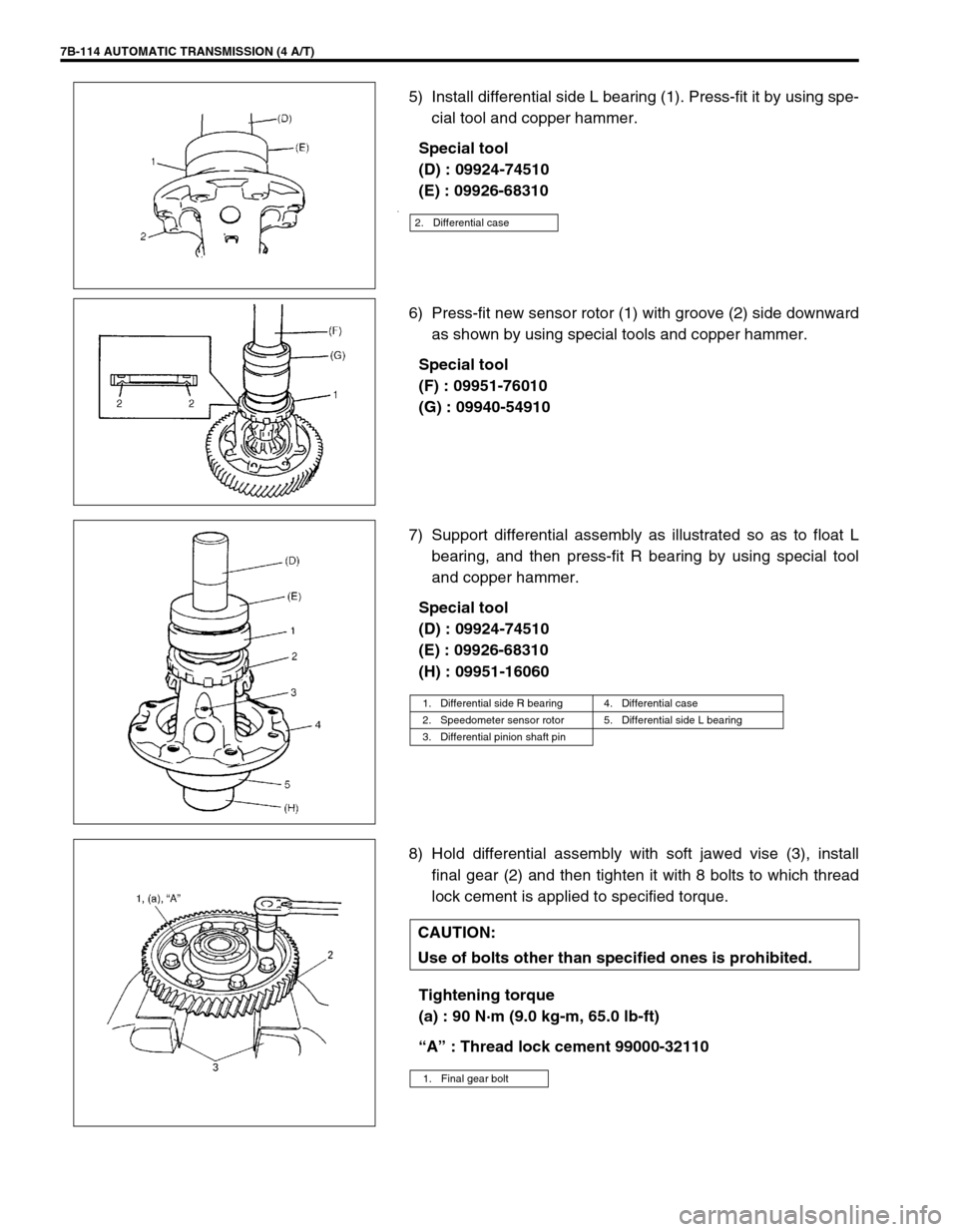
7B-114 AUTOMATIC TRANSMISSION (4 A/T)
5) Install differential side L bearing (1). Press-fit it by using spe-
cial tool and copper hammer.
Special tool
(D) : 09924-74510
(E) : 09926-68310
.
6) Press-fit new sensor rotor (1) with groove (2) side downward
as shown by using special tools and copper hammer.
Special tool
(F) : 09951-76010
(G) : 09940-54910
7) Support differential assembly as illustrated so as to float L
bearing, and then press-fit R bearing by using special tool
and copper hammer.
Special tool
(D) : 09924-74510
(E) : 09926-68310
(H) : 09951-16060
8) Hold differential assembly with soft jawed vise (3), install
final gear (2) and then tighten it with 8 bolts to which thread
lock cement is applied to specified torque.
Tightening torque
(a) : 90 N·m (9.0 kg-m, 65.0 lb-ft)
“A” : Thread lock cement 99000-32110
2. Differential case
1. Differential side R bearing 4. Differential case
2. Speedometer sensor rotor 5. Differential side L bearing
3. Differential pinion shaft pin
CAUTION:
Use of bolts other than specified ones is prohibited.
1. Final gear bolt
Page 167 of 447
AUTOMATIC TRANSMISSION (4 A/T) 7B-125
26) Attach parking lock rod (2) to manual shift shaft (1).
27) Install manual shift shaft and washer (3) to transmission
case. Fix manual shift shaft with washer, control shift lever
(4) and two nuts (5).
Apply grease to the washers.
Tightening torque
Control shift lever nuts
(a) : 30 N·m (3.0 kg-m, 22.0 lb-ft)
“A” : Grease 99000-25030
28) Install detent spring (1) to transmission case.
Tightening torque
Detent spring bolt (a) : 11 N·m (1.1 kg-m, 8.0 lb-ft)
29) Install thrust needle roller bearing (2) on counter bearing (3).
30) Install counter driven gear (1).
31) Install parking lock pawl sleeve (1) and oil plate (not shown
in figure).
Tightening torque
Parking lock pawl sleeve bolt
(a) : 19 N·m (1.9 kg-m, 14.0 lb-ft)
Page 168 of 447
7B-126 AUTOMATIC TRANSMISSION (4 A/T)
32) Install parking lock pawl (2).
33) Install parking lock pawl shaft (4), torsional spring (3), and
cover (1), then hold them with 2 bolts.
Tightening torque
Parking lock pawl bolts (a) : 11 N·m (1.1 kg-m, 8.0 lb-ft)
34) Install reverse brake (B2) plates, discs, flange and cushion
plate in following order :
(1) Cushion plate →
(2) Plate →
(3) Disc →
(4) Plate →
(5)
Disc →
(6) Plate →
(7) Disc →
(8) Plate →
(9) Disc →
(10)
Flange
35) Hold above parts with snap ring.
NOTE:
Note the direction of cushion plate (1).
Make sure that the plates are fitted into groove of
transmission case as shown in figure.
2. Brake plate side
3. Transmission case side
Page 172 of 447
7B-130 AUTOMATIC TRANSMISSION (4 A/T)
49) Install differential gear assembly (1).
50) Install thrust bearing race (1) and thrust needle roller bearing
(2) to the top of counter driven gear (3).
51) Apply grease to oil pump D-ring.
Install new gasket to transmission case and install torque
converter housing (1).
Tightening torque
Torque converter housing bolts
(h) : 19 N·m (1.9 kg-m, 14.0 lb-ft)
Grease 99000-25030
“A” : Thread lock cement 99000-32110 NOTE:
Grease can be applied around the R and L bearing of dif-
ferential gear assembly to ease fitting to the transmis-
sion case and torque converter housing.
NOTE:
Apply thread lock to the three bolts shown in figure.
2. New bolt
Page 174 of 447
7B-132 AUTOMATIC TRANSMISSION (4 A/T)
56) Install valve body assembly (1) to transmission case.
First match the pin of the manual valve to the slot of the
manual shift shaft.
To fix valve body assembly (1) to transmission case, first
tighten bolt B (3), then tighten other bolts.
Tightening torque
Valve body to transmission case bolts
: 10 N·m (1.0 kg-m, 7.5 lb-ft)
57) Connect couplers of wire-to-solenoid to solenoid valves.Bolt Length “a”Pieces
A 30 mm (1.20 in.) 7
B 31 mm (1.22 in.) 2
C 25 mm (0.98 in.) 2
2. Bolt A
4. Bolt C
5. Manual valve pin
6. Slot of manual shift shaft
Solenoid Valve Wire Color
A (No.1) White
B (No.2) Black
C (No.3) Red
D (No.4) Yellow
E (No.5) Brown
TCC (Lock-up) Orange
1. Solenoid valve No.1
2. Solenoid valve No.2
3. Solenoid valve No.3
4. Solenoid valve No.4
5. Solenoid valve No.5
6. Lock-up solenoid
Page 178 of 447

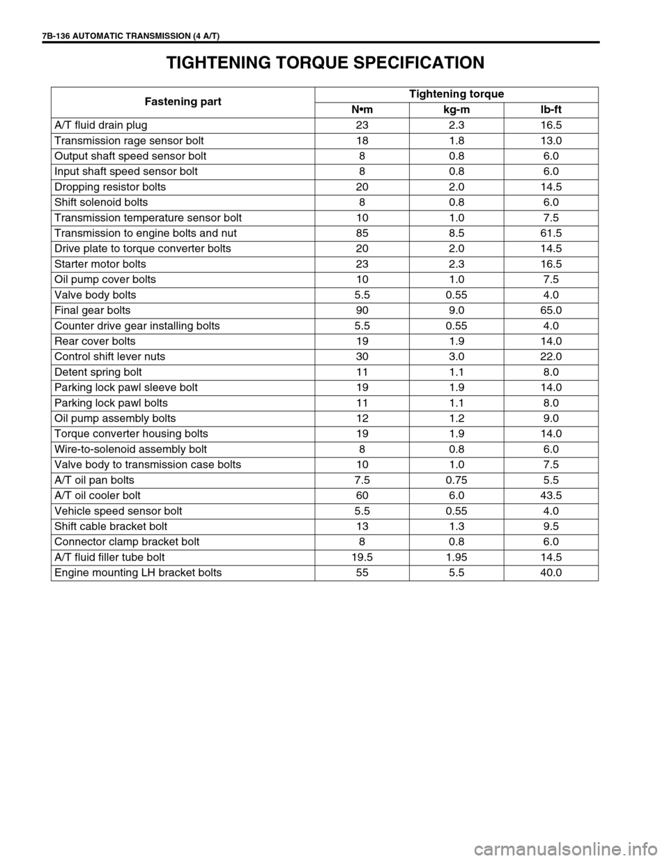
7B-136 AUTOMATIC TRANSMISSION (4 A/T)
TIGHTENING TORQUE SPECIFICATION
Fastening partTightening torque
Nm kg-m lb-ft
A/T fluid drain plug 23 2.3 16.5
Transmission rage sensor bolt 18 1.8 13.0
Output shaft speed sensor bolt 8 0.8 6.0
Input shaft speed sensor bolt 8 0.8 6.0
Dropping resistor bolts 20 2.0 14.5
Shift solenoid bolts 8 0.8 6.0
Transmission temperature sensor bolt 10 1.0 7.5
Transmission to engine bolts and nut 85 8.5 61.5
Drive plate to torque converter bolts 20 2.0 14.5
Starter motor bolts 23 2.3 16.5
Oil pump cover bolts 10 1.0 7.5
Valve body bolts 5.5 0.55 4.0
Final gear bolts 90 9.0 65.0
Counter drive gear installing bolts 5.5 0.55 4.0
Rear cover bolts 19 1.9 14.0
Control shift lever nuts 30 3.0 22.0
Detent spring bolt 11 1.1 8.0
Parking lock pawl sleeve bolt 19 1.9 14.0
Parking lock pawl bolts 11 1.1 8.0
Oil pump assembly bolts 12 1.2 9.0
Torque converter housing bolts 19 1.9 14.0
Wire-to-solenoid assembly bolt 8 0.8 6.0
Valve body to transmission case bolts 10 1.0 7.5
A/T oil pan bolts 7.5 0.75 5.5
A/T oil cooler bolt 60 6.0 43.5
Vehicle speed sensor bolt 5.5 0.55 4.0
Shift cable bracket bolt 13 1.3 9.5
Connector clamp bracket bolt 8 0.8 6.0
A/T fluid filler tube bolt 19.5 1.95 14.5
Engine mounting LH bracket bolts 55 5.5 40.0