Page 108 of 447
7B-66 AUTOMATIC TRANSMISSION (4 A/T)
6) Disconnect shift solenoid couplers.
7) Remove shift solenoid valves.
SHIFT SOLENOID VALVES
INSPECTION
Resistance Check
Shift solenoid A (No.1), B (No.2) and lock-up solenoid
Resistance between terminal and solenoid body
Standard : 10.5 – 15.5
Ω
ΩΩ Ω
Shift solenoid C (No.3), D (No.4) or E (No.5)
Resistance between terminal and solenoid body
Standard : 2.5 – 3.5
Ω
ΩΩ Ω
Operation check
When solenoids is connected to the battery as shown in figure,
check that the solenoid actuates with a click sound.
TRANSMISSION TEMPERATURE SENSOR
INSPECTION
Warm up transmission temp. sensor. Thus make sure its resis-
tance decrease with the increase of temperature.
Transmission temperature sensor resistance
1. Solenoid valve
1. Solenoid valve
Temperature Resistance
20°C (68°F) 2.5 k
Ω
ΩΩ Ω
40°C (104°F) 1.2 k
Ω
ΩΩ Ω
60°C (140°F) 0.6 k
Ω
ΩΩ Ω
1. Transmission temperature sensor coupler
Page 109 of 447
AUTOMATIC TRANSMISSION (4 A/T) 7B-67
INSTALLATION
1) Install shift solenoid valves.
Tightening torque
Solenoid valve bolts (a) : 8 N·m (0.8 kg-m, 6.0 lb-ft)
2) Connect shift solenoid couplers.
3) Install oil strainer (2) and transmission temperature sensor
(1).
Tightening torque
Transmission temperature sensor bolt
(b) : 10 N·m (1.0 kg-m, 7.5 lb-ft)
4) Connect transmission temperature sensor coupler (3).
5) Clean mating surface of A/T oil pan (1) and A/T case.
6) Install new gasket (2) to A/T oil pan.
7) Install A/T oil pan.
Tightening torque
A/T oil pan bolts (a) : 7.5 N·m (0.75 kg-m, 5.5 lb-ft)
8) Install A/T fluid drain bolt.
Tightening torque
A/T fluid drain bolt (b) : 23 N·m (2.3 kg-m, 16.5 lb-ft)
9) Refill A/T fluid referring to “FLUID CHANGE” in this section.
10) Verify that there is no A/T fluid leakage.
NOTE:
Do not forget to install O-ring (4) to oil strainer first.
Page 121 of 447
AUTOMATIC TRANSMISSION (4 A/T) 7B-79
4) Remove output shaft speed sensor (1) and input shaft speed
sensor (2).
5) Remove transmission range sensor (3).
6) Remove dropping resistor (4).
7) Remove breather hose (5).
8) Remove A/T fluid level gauge (1) and filler tube (2).
9) Remove vehicle speed sensor (1) (for speedometer), shift
cable bracket (2) and connector clamp bracket (3).
10) Remove oil pan and oil pan gasket.
11) Remove oil strainer assembly (1), and detach transmission
temperature sensor (2).
NOTE:
For removal of oil pan, do not turn transmission over
as this will contaminate valve body with foreign materi-
als in the bottom of oil pan.
When removing oil pan, tap around it lightly with a
plastic hammer. Do not force it off by using a screw-
driver or the like.
Page 122 of 447

7B-80 AUTOMATIC TRANSMISSION (4 A/T)
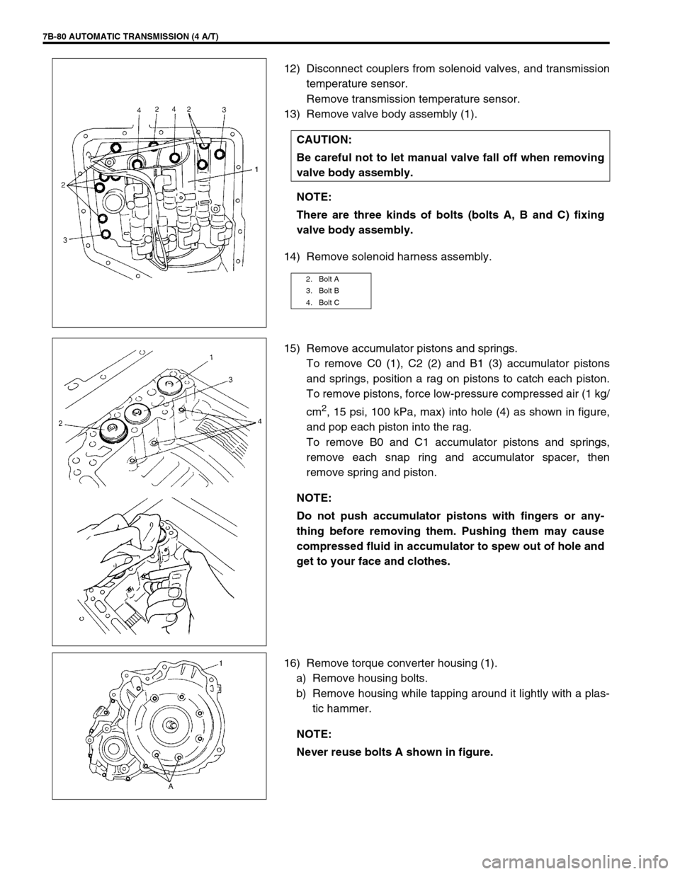
12) Disconnect couplers from solenoid valves, and transmission
temperature sensor.
Remove transmission temperature sensor.
13) Remove valve body assembly (1).
14) Remove solenoid harness assembly.
15) Remove accumulator pistons and springs.
To remove C0 (1), C2 (2) and B1 (3) accumulator pistons
and springs, position a rag on pistons to catch each piston.
To remove pistons, force low-pressure compressed air (1 kg/
cm
2, 15 psi, 100 kPa, max) into hole (4) as shown in figure,
and pop each piston into the rag.
To remove B0 and C1 accumulator pistons and springs,
remove each snap ring and accumulator spacer, then
remove spring and piston.
16) Remove torque converter housing (1).
a) Remove housing bolts.
b) Remove housing while tapping around it lightly with a plas-
tic hammer. CAUTION:
Be careful not to let manual valve fall off when removing
valve body assembly.
NOTE:
There are three kinds of bolts (bolts A, B and C) fixing
valve body assembly.
2. Bolt A
3. Bolt B
4. Bolt C
NOTE:
Do not push accumulator pistons with fingers or any-
thing before removing them. Pushing them may cause
compressed fluid in accumulator to spew out of hole and
get to your face and clothes.
NOTE:
Never reuse bolts A shown in figure.
Page 154 of 447
7B-112 AUTOMATIC TRANSMISSION (4 A/T)
DIFFERENTIAL ASSEMBLY
Servicing procedure for differential assembly is similar to that for manual transmission. Refer to Section 7A of
this manual for adjustment procedure.
DISASSEMBLY
1) Remove R bearing and then speed sensor rotor using spe-
cial tool and puller.
Special tool
(A) : 09925-88210
2) Hold differential assembly with soft jawed vise, remove final
gear (1).
1. Differential pinion 7. Differential right side bearing (R bearing) 13. Pinion shaft pin
2. Differential gear
8. Speedometer sensor rotor Apply automatic transmission fluid.
3. Washer (for pinion)
9. Differential case Tightening torque
4. Pinion shaft
10. Final gear Do not reuse.
5. Washer (for gear) 11. Bolt
6. Differential side oil seal
: Apply grease 99000-25030 to oil seal lip.
12. Differential left side bearing (L bearing)
1. Differential gear assembly
Page 156 of 447

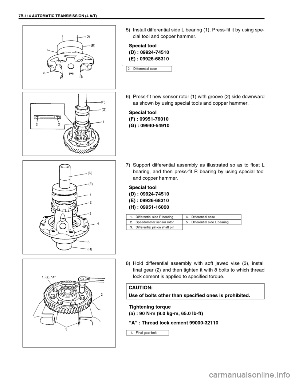
7B-114 AUTOMATIC TRANSMISSION (4 A/T)
5) Install differential side L bearing (1). Press-fit it by using spe-
cial tool and copper hammer.
Special tool
(D) : 09924-74510
(E) : 09926-68310
.
6) Press-fit new sensor rotor (1) with groove (2) side downward
as shown by using special tools and copper hammer.
Special tool
(F) : 09951-76010
(G) : 09940-54910
7) Support differential assembly as illustrated so as to float L
bearing, and then press-fit R bearing by using special tool
and copper hammer.
Special tool
(D) : 09924-74510
(E) : 09926-68310
(H) : 09951-16060
8) Hold differential assembly with soft jawed vise (3), install
final gear (2) and then tighten it with 8 bolts to which thread
lock cement is applied to specified torque.
Tightening torque
(a) : 90 N·m (9.0 kg-m, 65.0 lb-ft)
“A” : Thread lock cement 99000-32110
2. Differential case
1. Differential side R bearing 4. Differential case
2. Speedometer sensor rotor 5. Differential side L bearing
3. Differential pinion shaft pin
CAUTION:
Use of bolts other than specified ones is prohibited.
1. Final gear bolt
Page 175 of 447
AUTOMATIC TRANSMISSION (4 A/T) 7B-133
58) Install O-ring to oil strainer assembly (1). Make sure that O-
ring is not twisted.
59) Install oil strainer assembly to the top of valve body assem-
bly.
Connect transmission temperature sensor (2) coupler.
Fix transmission temperature sensor and oil strainer assem-
bly with bolts.
Tightening torque
Transmission temperature sensor bolt
(a) : 10 N·m (1.0 kg-m, 7.5 lb-ft)
60) Install magnet (1) in oil pan (2).
61) Install gasket to transmission case and install oil pan (1).
Tightening torque
A/T oil pan bolts (a) : 7.5 N·m (0.75 kg-m, 5.5 lb-ft)
62) Install oil cooler (1) and ground cable (2).
Tightening torque
A/T oil cooler bolt (a): 60 N·m (6.0 kg-m, 43.5 lb-ft)
NOTE:
If metal particles are attached to the magnet, clean them
before installing.
Page 176 of 447
7B-134 AUTOMATIC TRANSMISSION (4 A/T)
63) Install vehicle speed sensor (for speedometer) (1), shift
cable bracket (2) and connector clamp bracket (3).
Tightening torque
Vehicle speed sensor bolt
(a) : 5.5 N·m (0.55 kg-m, 4.0 lb-ft)
Shift cable bracket bolts
(b) : 13 N·m (1.3 kg-m, 9.5 lb-ft)
Connector clamp bracket bolt : 8 N·m (0.8 kg-m, 6.0 lb-ft)
64) Install A/T fluid filler tube (2) and level gauge (1).
Tightening torque
A/T fluid filler tube bolt (a) : 19.5 N·m (1.95 kg-m, 14.5 lb-ft)
65) Install output shaft speed sensor (1) and input shaft speed
sensor (2).
Apply grease to O-ring of each sensor.
Tightening torque
Output shaft speed sensor bolt
(a) : 8 N·m (0.8 kg-m, 6.0 lb-ft)
Input shaft speed sensor bolt
(b) : 8 N·m (0.8 kg-m, 6.0 Ib-ft)
Grease : 99000-25030
66) Install engine mounting LH bracket.
Tightening torque
Engine mounting LH bracket bolts
(a) : 55 N·m (5.5 kg-m, 40.0 lb-ft)