2000 SUZUKI SWIFT service
[x] Cancel search: servicePage 1 of 447

MANUAL TRANSMISSION 7A-1
6F1
6F2
6G
6H
6K
7A1
7B1
7C1
7A
7E
7F
8A
8B
8C
8D
8E
9
10
10A
10B
SECTION 7A
MANUAL TRANSMISSION
CONTENTS
GENERAL DESCRIPTION .............................. 7A-2
CONSTRUCTION AND SERVICING ........... 7A-2
TRANSMISSION FOR 2WD MODEL....... 7A-3
TRANSMISSION FOR 4WD MODEL....... 7A-4
DIAGNOSIS ..................................................... 7A-5
ON-VEHICLE SERVICE .................................. 7A-5
OIL CHANGE ............................................... 7A-6
DIFFERENTIAL SIDE OIL SEAL ................. 7A-6
GEAR SHIFT CONTROL LEVER AND
CABLE ......................................................... 7A-8
VEHICLE SPEED SENSOR (VSS) ............ 7A-10
UNIT REPAIR OVERHAUL ........................... 7A-11
TRANSMISSION UNIT............................... 7A-11
TRASMISSION CASE ................................ 7A-12
INPUT & COUNTER SHAFT...................... 7A-13
GEAR SHIFTER & DIFFERENTIAL ........... 7A-14
TRANSMISSION UNIT............................... 7A-16
UNIT DISASSEMBLY ................................ 7A-17
FIFTH GEARS........................................ 7A-17GEAR SHIFTER, INPUT SHAFT AND
COUNTER SHAFT................................. 7A-19
RIGHT CASE ......................................... 7A-20
SUB ASSEMBLY SERVICE ...................... 7A-21
RIGHT CASE ......................................... 7A-21
LEFT CASE............................................ 7A-21
INPUT SHAFT ASSEMBLY ................... 7A-22
COUNTER SHAFT ASSEMBLY ............ 7A-25
GEAR SHIFTER..................................... 7A-29
DIFFERENTIAL ASSEMBLY ................. 7A-30
UNIT ASSEMBLY ...................................... 7A-33
DIFFERENTIAL TO LEFT CASE ........... 7A-33
FIFTH GEARS ....................................... 7A-35
GEAR SHIFT AND SELECT SHAFT
ASSEMBLY ............................................ 7A-38
TIGHTENING TORQUE SPECIFICATION.... 7A-39
REQUIRED SERVICE MATERIAL................ 7A-40
SPECIAL TOOL ............................................ 7A-40
WARNING:
For vehicles equipped with Supplemental Restraint (Air Bag) System :
• Service on and around the air bag system components or wiring must be performed only by an
authorized SUZUKI dealer. Refer to “Air Bag System Components and Wiring Location View” under
“General Description” in air bag system section in order to confirm whether you are performing ser-
vice on or near the air bag system components or wiring. Please observe all WARNINGS and “Ser-
vice Precautions” under “On-Vehicle Service” in air bag system section before performing service
on or around the air bag system components or wiring. Failure to follow WARNINGS could result in
unintentional activation of the system or could render the system inoperative. Either of these two
conditions may result in severe injury.
Technical service work must be started at least 90 seconds after the ignition switch is turned to the
“LOCK” position and the negative cable is disconnected from the battery. Otherwise, the system
may be activated by reserve energy in the Sensing and Diagnostic Module (SDM).
Page 5 of 447

MANUAL TRANSMISSION 7A-5
DIAGNOSIS
ON-VEHICLE SERVICE
Condition Possible Cause Correction
Gears slipping out of
meshMaladjusted gear shift/select control cables Adjust.
Worn shift fork shaft Replace.
Worn shift fork or synchronizer sleeve Replace.
Weak or damaged locating springs Replace.
Worn bearings on input shaft or counter shaft Replace.
Worn chamfered tooth on sleeve and gear Replace sleeve and gear.
Hard shifting
Maladjusted gear shift/select control cables Adjust.
Inadequate or insufficient lubricant Replenish.
Improper clutch pedal free travel Adjust.
Distorted or broken clutch disc Replace.
Damaged clutch pressure plate Replace clutch cover.
Worn synchronizer ring Replace.
Worn chamfered tooth on sleeve or gear Replace sleeve or gear.
Worn gear shift/select control cables joint Replace.
Distorted shift shaft Replace.
Noise
Inadequate or insufficient lubricant Replenish.
Damaged or worn bearing(s) Replace.
Damaged or worn gear(s) Replace.
Damaged or worn synchronizer parts Replace.
CAUTION:
Do not reuse circlip, spring pin, E-ring, oil seal, gasket,
self locking nut and specified parts. Reuse of it can result
in trouble.
Page 6 of 447

7A-6 MANUAL TRANSMISSION
OIL CHANGE
1) Before changing or inspecting oil, be sure to stop engine and
lift vehicle horizontally.
2) With vehicle lifted up, check oil level and leakage.
If leakage exists, correct it.
3) Drain old oil and fill new specified oil by specified amount (up
to level hole).
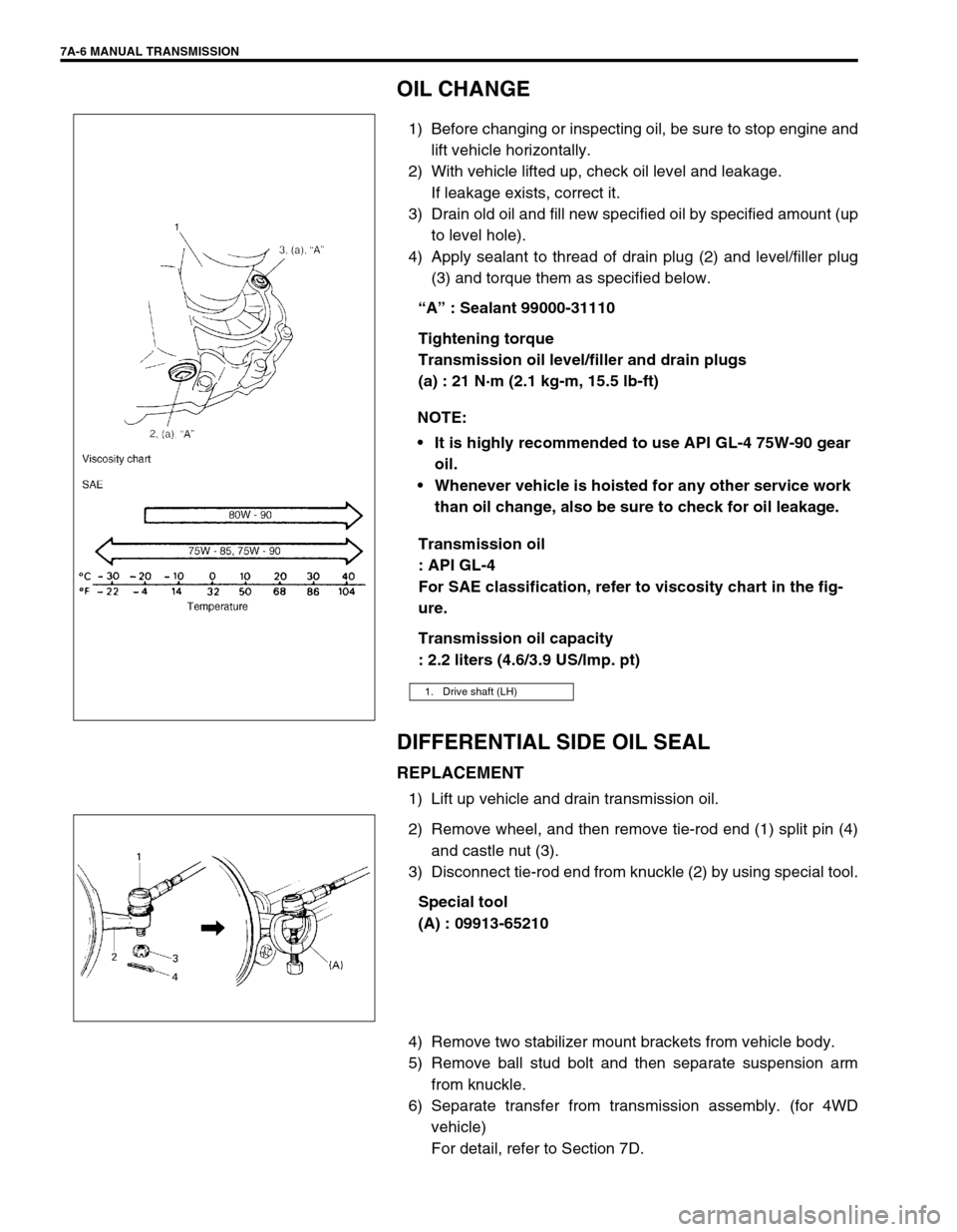
4) Apply sealant to thread of drain plug (2) and level/filler plug
(3) and torque them as specified below.
“A” : Sealant 99000-31110
Tightening torque
Transmission oil level/filler and drain plugs
(a) : 21 N·m (2.1 kg-m, 15.5 lb-ft)
Transmission oil
: API GL-4
For SAE classification, refer to viscosity chart in the fig-
ure.
Transmission oil capacity
: 2.2 liters (4.6/3.9 US/lmp. pt)
DIFFERENTIAL SIDE OIL SEAL
REPLACEMENT
1) Lift up vehicle and drain transmission oil.
2) Remove wheel, and then remove tie-rod end (1) split pin (4)
and castle nut (3).
3) Disconnect tie-rod end from knuckle (2) by using special tool.
Special tool
(A) : 09913-65210
4) Remove two stabilizer mount brackets from vehicle body.
5) Remove ball stud bolt and then separate suspension arm
from knuckle.
6) Separate transfer from transmission assembly. (for 4WD
vehicle)
For detail, refer to Section 7D. NOTE:
It is highly recommended to use API GL-4 75W-90 gear
oil.
Whenever vehicle is hoisted for any other service work
than oil change, also be sure to check for oil leakage.
1. Drive shaft (LH)
Page 21 of 447

MANUAL TRANSMISSION 7A-21
SUB ASSEMBLY SERVICE
RIGHT CASE
1) Install input shaft oil seal (1) facing its spring side upward.
Use special tool and hammer for installation and apply
grease to oil seal lip.
“B” : Grease 99000-25010
Special tool
(A) : 09951-76010
2) Install countershaft right bearing cup (2) by using special
tools and hammer.
Special tool
(B) : 09924-74510
(C) : 09925-68210
LEFT CASE
1) If input oil gutter has been removed, install it with bolt to
which thread lock cement have been applied.
“A” : Thread lock cement 99000-32110
Tightening torque
Oil gutter bolt (a) : 10 N·m (1.0 kg-m, 7.5 lb-ft)
2) Install differential side left oil seal (1) facing its spring side
inward until it becomes flush with case surface by using spe-
cial tool with hammer, and then apply grease to its lip.
“B” : Grease 99000-25010
Special tool
(A) : 09913-75510
3) Install counter shaft left bearing cup into case bore by tap-
ping it with plastic hammer lightly. NOTE:
Before installation, wash each part and apply specified
gear oil to sliding faces of bearing and gear.
Page 23 of 447

MANUAL TRANSMISSION 7A-23
INSPECTION AND REASSEMBLY
1) Clean all components thoroughly, inspect them for any
abnormality and replace with new ones as necessary.
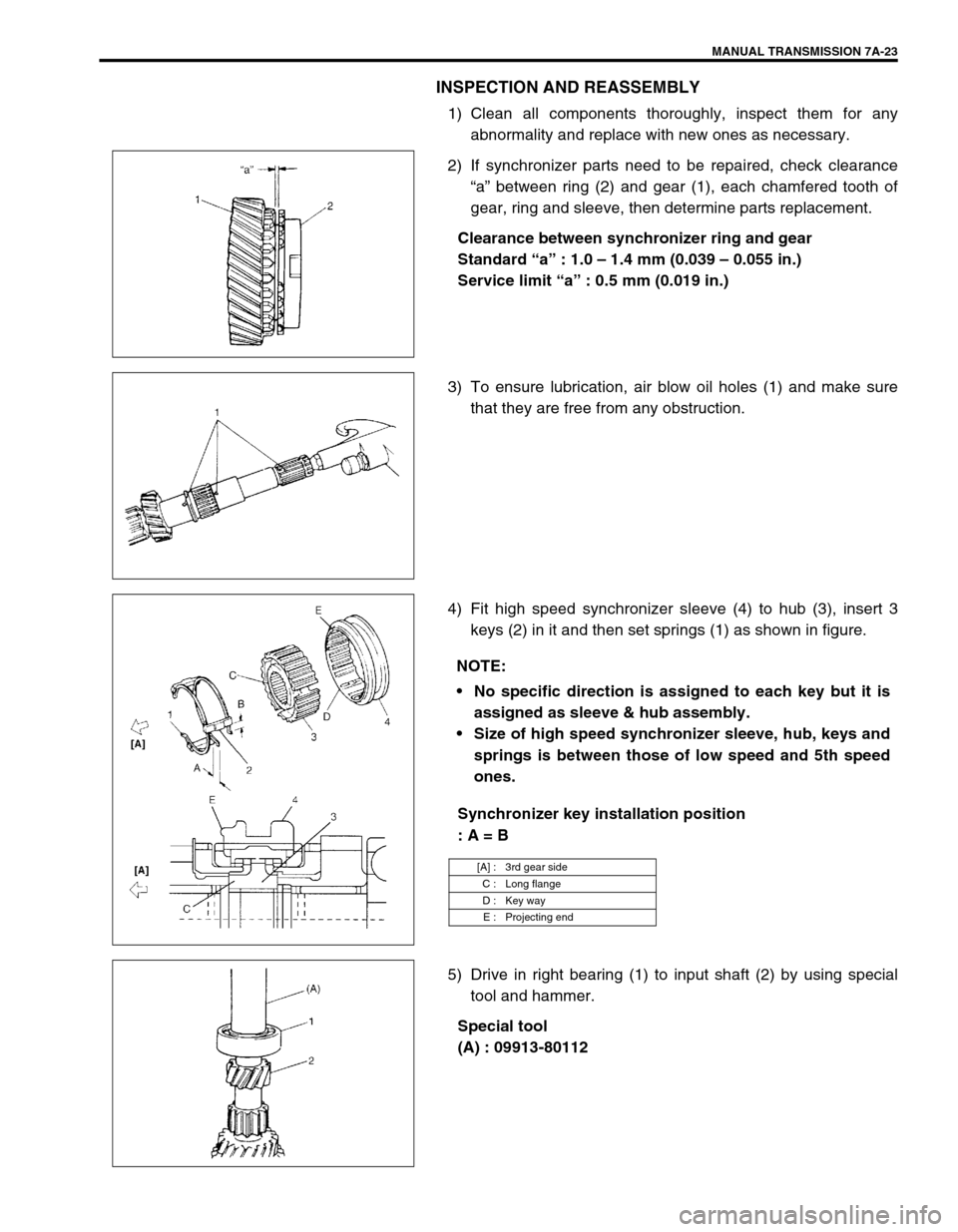
2) If synchronizer parts need to be repaired, check clearance
“a” between ring (2) and gear (1), each chamfered tooth of
gear, ring and sleeve, then determine parts replacement.
Clearance between synchronizer ring and gear
Standard “a” : 1.0 – 1.4 mm (0.039 – 0.055 in.)
Service limit “a” : 0.5 mm (0.019 in.)
3) To ensure lubrication, air blow oil holes (1) and make sure
that they are free from any obstruction.
4) Fit high speed synchronizer sleeve (4) to hub (3), insert 3
keys (2) in it and then set springs (1) as shown in figure.
Synchronizer key installation position
: A = B
5) Drive in right bearing (1) to input shaft (2) by using special
tool and hammer.
Special tool
(A) : 09913-80112
NOTE:
No specific direction is assigned to each key but it is
assigned as sleeve & hub assembly.
Size of high speed synchronizer sleeve, hub, keys and
springs is between those of low speed and 5th speed
ones.
[A] : 3rd gear side
C : Long flange
D : Key way
E : Projecting end
Page 26 of 447

7A-26 MANUAL TRANSMISSION
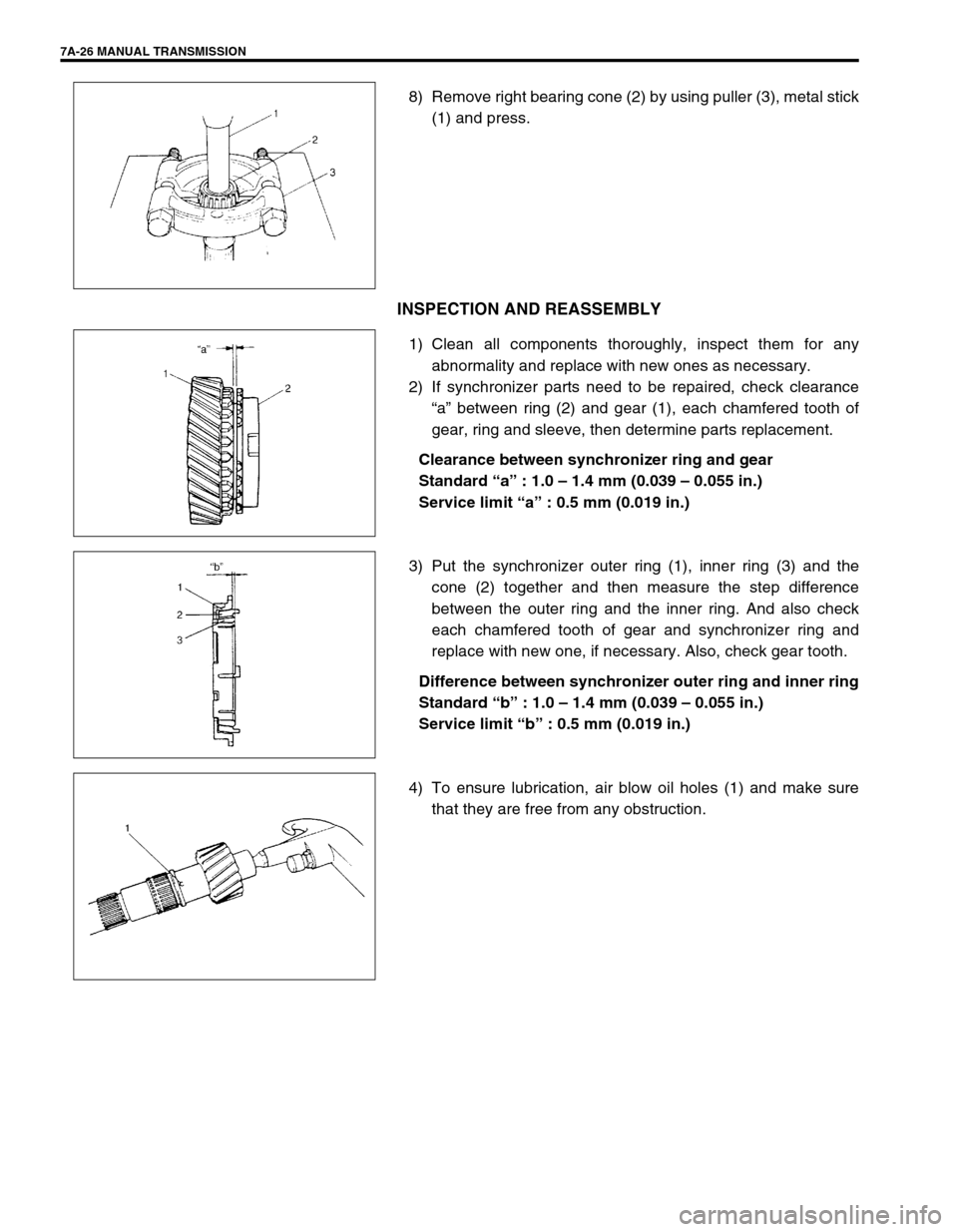
8) Remove right bearing cone (2) by using puller (3), metal stick
(1) and press.
INSPECTION AND REASSEMBLY
1) Clean all components thoroughly, inspect them for any
abnormality and replace with new ones as necessary.
2) If synchronizer parts need to be repaired, check clearance
“a” between ring (2) and gear (1), each chamfered tooth of
gear, ring and sleeve, then determine parts replacement.
Clearance between synchronizer ring and gear
Standard “a” : 1.0 – 1.4 mm (0.039 – 0.055 in.)
Service limit “a” : 0.5 mm (0.019 in.)
3) Put the synchronizer outer ring (1), inner ring (3) and the
cone (2) together and then measure the step difference
between the outer ring and the inner ring. And also check
each chamfered tooth of gear and synchronizer ring and
replace with new one, if necessary. Also, check gear tooth.
Difference between synchronizer outer ring and inner ring
Standard “b” : 1.0 – 1.4 mm (0.039 – 0.055 in.)
Service limit “b” : 0.5 mm (0.019 in.)
4) To ensure lubrication, air blow oil holes (1) and make sure
that they are free from any obstruction.
Page 29 of 447

MANUAL TRANSMISSION 7A-29
GEAR SHIFTER
Gear Shift and Select Shaft Assembly
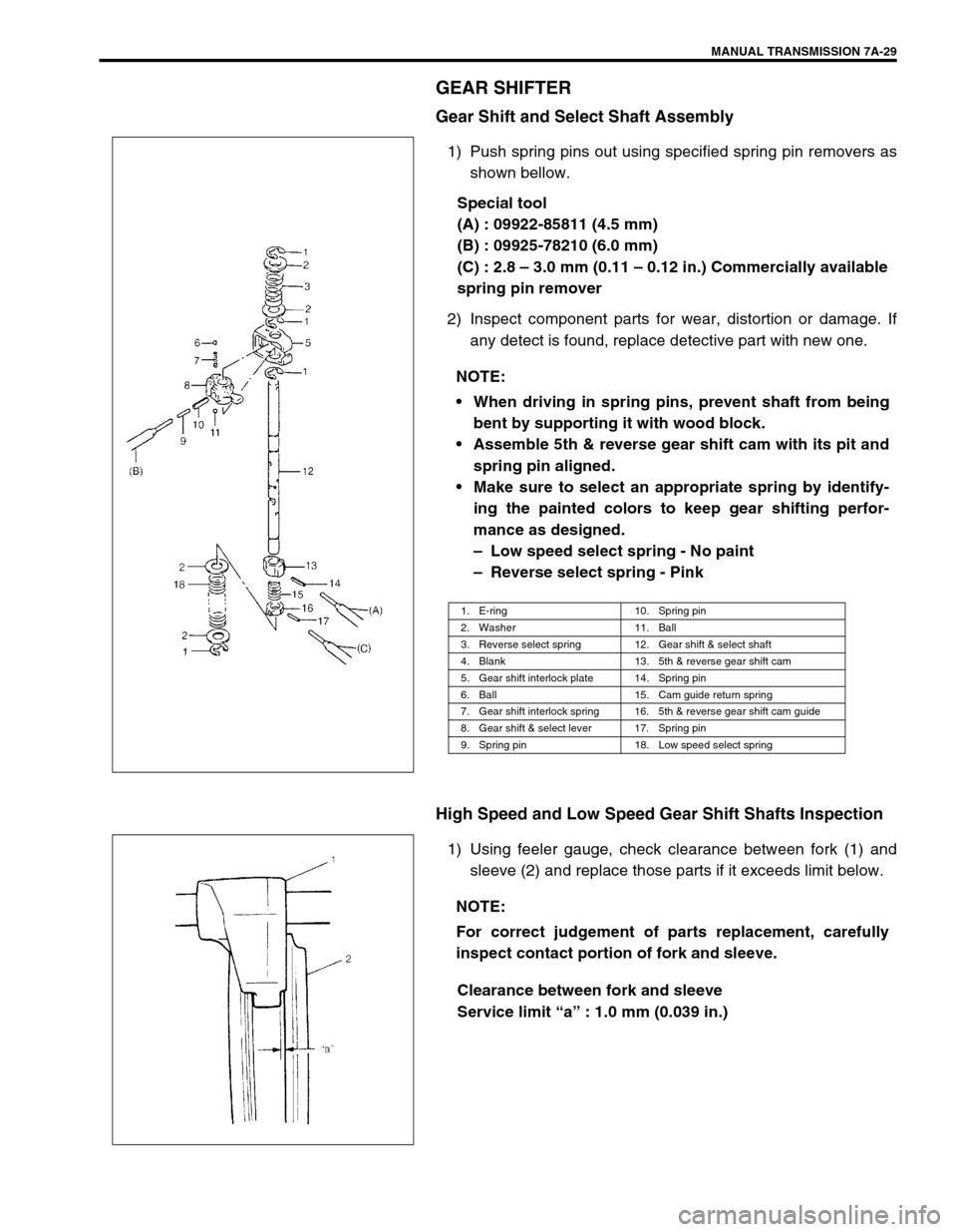
1) Push spring pins out using specified spring pin removers as
shown bellow.
Special tool
(A) : 09922-85811 (4.5 mm)
(B) : 09925-78210 (6.0 mm)
(C) : 2.8 – 3.0 mm (0.11 – 0.12 in.) Commercially available
spring pin remover
2) Inspect component parts for wear, distortion or damage. If
any detect is found, replace detective part with new one.
High Speed and Low Speed Gear Shift Shafts Inspection
1) Using feeler gauge, check clearance between fork (1) and
sleeve (2) and replace those parts if it exceeds limit below.
Clearance between fork and sleeve
Service limit “a” : 1.0 mm (0.039 in.) NOTE:
When driving in spring pins, prevent shaft from being
bent by supporting it with wood block.
Assemble 5th & reverse gear shift cam with its pit and
spring pin aligned.
Make sure to select an appropriate spring by identify-
ing the painted colors to keep gear shifting perfor-
mance as designed.
– Low speed select spring - No paint
– Reverse select spring - Pink
1. E-ring 10. Spring pin
2. Washer 11. Ball
3. Reverse select spring 12. Gear shift & select shaft
4. Blank 13. 5th & reverse gear shift cam
5. Gear shift interlock plate 14. Spring pin
6. Ball 15. Cam guide return spring
7. Gear shift interlock spring 16. 5th & reverse gear shift cam guide
8. Gear shift & select lever 17. Spring pin
9. Spring pin 18. Low speed select spring
NOTE:
For correct judgement of parts replacement, carefully
inspect contact portion of fork and sleeve.
Page 35 of 447

MANUAL TRANSMISSION 7A-35
11) Check locating spring for deterioration and replace with new
one as necessary.
Locating spring free length
For Low speed (3) and 5th & reverse (6)
Standard : 26.1 mm (1.028 in.)
Service Limit : 25.0 mm (0.984 in.)
For High speed (5)
Standard : 40.1 mm (1.579 in.)
Service Limit : 39.0 mm (1.535 in.)
12) Install steel ball (4) and locating spring for respective gear
shift shaft and tighten bolt (1) to which sealant have been
applied to its thread part.
Sealant 99000-31110
Tightening torque
Locating spring bolts (d) : 13 N·m (1.3 kg-m, 9.5 Ib-ft)
FIFTH GEARS
1) To seat countershaft left bearing cup (1) to bearing cone, tap
cup by using special tool and plastic hammer.
Special tool
(A) : 09913-84510
2) Put a shim (2) on bearing cup (3) provisionally, place straight
edge (1) over it and compress it by hand through straight
edge, and then measure “a” (Clearance between case sur-
face (4) and straight edge) by using feeler gauge (5).
Clearance between case surface and straight edge
“a” : 0.13 – 0.17 mm (0.0051 – 0.0067 in.)
(Shim protrusion)
3) By repeating above step, select a suitable shim which
adjusts clearance “a” to specification and put it on bearing
cup.
2. Washer
NOTE:
Insert 0.15 mm (0.0059 in.) feeler to know whether or not
a shim fulfills specification quickly.