2000 SUZUKI SWIFT service
[x] Cancel search: servicePage 220 of 447

7D-22 TRANSFER
TIGHTENING TORQUE SPECIFICATION
REQUIRED SERVICE MATERIAL
SPECIAL TOOL
Fastening partTightening torque
Nm kg-m lb-ft
Transfer oil level/filler and drain plugs 21 2.1 15.5
Transfer bevel gear nut 150 15.0 108.5
Transfer case bolts 23 2.3 17.0
Transfer output retainer bolts 50 5.0 36.5
Transfer mounting bolts 50 5.0 36.5
Transfer rear mounting bracket bolts 55 5.5 40.0
Transfer rear mounting bracket nuts 50 5.5 36.5
Transfer mounting bolt 55 5.5 40.0
Transfer rear mounting bracket No.2 bolts 55 5.5 40.0
Transfer stiffener bolts 50 5.0 36.5
Exhaust pipe bolts 50 5.0 36.5
MaterialRecommended SUZUKI products
(Part Number)Use
Lithium grease SUZUKI SUPER GREASE A
(99000-25010)Oil seal lips
Sealant SUZUKI BOND NO. 1216B
(99000-31230)Oil drain plug
Oil level plug
Mating surface of transfer case
09913-65135 09925-58210 09941-54911 09924-84510-005
Bearing puller Oil seal installer Bearing outer race
removerBearing installer attach-
ment
Page 223 of 447

REAR DIFFERENTIAL 7F-1
6F1
6F2
6G
6H
6K
7A
7A1
7B1
7C1
7E
7F
7F
8B
8C
8D
8E
9
10
10A
10B
SECTION 7F
REAR DIFFERENTIAL
CONTENTS
GENERAL DESCRIPTION ............................... 7F-2
VISCOUS COUPLING .................................. 7F-2
DIAGNOSIS ...................................................... 7F-3
ON-VEHICLE SERVICE ................................... 7F-4
OIL CHANGE ................................................ 7F-4
UNIT REPAIR OVERHAUL .............................. 7F-5
DIFFERENTIAL UNIT ................................... 7F-6
UNIT DISASSEMBLY ................................... 7F-7SUB-ASSEMBLY REPAIR............................ 7F-8
VISCOUS COUPLING .............................. 7F-8
REAR DIFFERENTIAL............................ 7F-10
UNIT ASSEMBLY ....................................... 7F-20
TIGHTENING TORQUE SPECIFICATION..... 7F-20
REQUIRED SERVICE MATERIAL................. 7F-21
SPECIAL TOOL ............................................. 7F-21
Page 226 of 447

7F-4 REAR DIFFERENTIAL
ON-VEHICLE SERVICE
OIL CHANGE
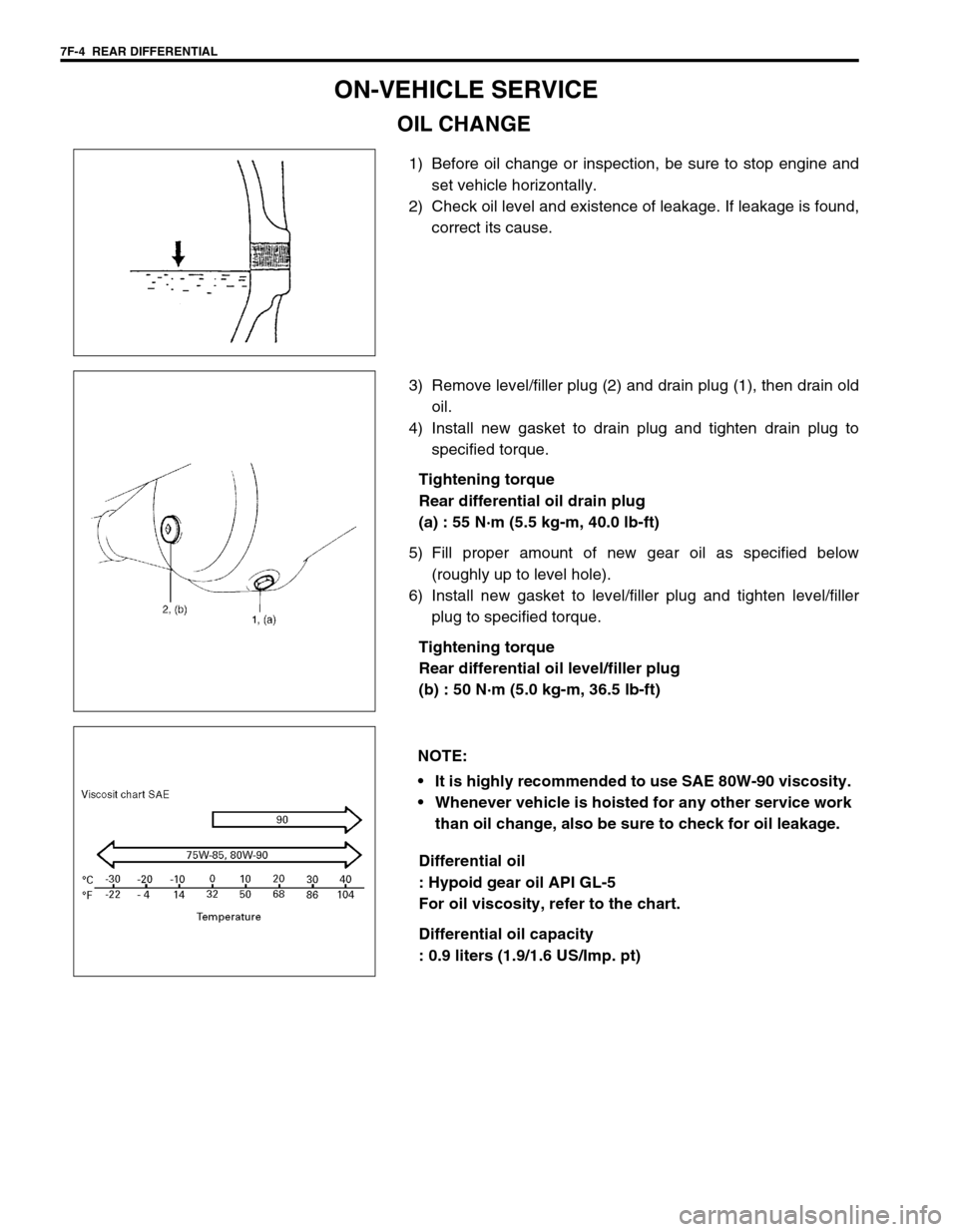
1) Before oil change or inspection, be sure to stop engine and
set vehicle horizontally.
2) Check oil level and existence of leakage. If leakage is found,
correct its cause.
3) Remove level/filler plug (2) and drain plug (1), then drain old
oil.
4) Install new gasket to drain plug and tighten drain plug to
specified torque.
Tightening torque
Rear differential oil drain plug
(a) : 55 N·m (5.5 kg-m, 40.0 lb-ft)
5) Fill proper amount of new gear oil as specified below
(roughly up to level hole).
6) Install new gasket to level/filler plug and tighten level/filler
plug to specified torque.
Tightening torque
Rear differential oil level/filler plug
(b) : 50 N·m (5.0 kg-m, 36.5 lb-ft)
Differential oil
: Hypoid gear oil API GL-5
For oil viscosity, refer to the chart.
Differential oil capacity
: 0.9 liters (1.9/1.6 US/Imp. pt)
NOTE:
It is highly recommended to use SAE 80W-90 viscosity.
Whenever vehicle is hoisted for any other service work
than oil change, also be sure to check for oil leakage.
Page 243 of 447

REAR DIFFERENTIAL 7F-21
REQUIRED SERVICE MATERIAL
SPECIAL TOOL
MaterialRecommended SUZUKI product
(Part Number)Use
Thread lock cement THREAD LOCK CEMENT 1322
(99000-32110)Bevel gear bolts
Lithium grease SUZUKI SUPER GREASE A
(99000-25010)Oil seal lips
Sealant SUZUKI BOND NO. 1215
(99000-31110)Thread part of differential carrier bolt
Mating surface of differential housing
Mating surface of rear axle housing
Mating surface of viscous coupling case
09951-16060 09951-76010 09927-28010 09925-88210
Lower arm bush remover Bearing installer Bevel pinion holder Bearing puller attachment
09913-60910 09913-80112 09900-20701 09900-20606
Bearing puller Bearing installer Magnetic stand Dial gauge
09922-76140 09922-76150 09922-76330 09922-76430
Bevel pinion shaft Bevel pinion nut Rear collar Front collar
Page 245 of 447

BODY ELECTRICAL SYSTEM 8-1
6F1
6F2
6G
6H
6K
7A
7A1
7B1
7C1
7D
7E
7F
8A
8
8D
8E
9
10
10A
10B
SECTION 8
BODY ELECTRICAL SYSTEM
CONTENTS
DIAGNOSIS ........................................................ 8-3
HEADLIGHT .................................................... 8-3
HEADLIGHTS WITH LEVELING SYSTEM
(IF EQUIPPED) ............................................... 8-3
TURN SIGNAL AND HAZARD WARNING
LIGHT .............................................................. 8-3
CLEARANCE, TAIL AND LICENSE
PLATE LIGHT ................................................. 8-4
BACK-UP LIGHT ............................................. 8-4
BRAKE LIGHT ................................................ 8-4
FRONT FOG LIGHT (IF EQUIPPED) ............. 8-4
REAR FOG LIGHT (IF EQUIPPED) ................ 8-4
SPEEDOMETER AND VSS ............................ 8-5
FUEL METER AND FUEL LEVEL SENSOR
(GAUGE UNIT) ............................................... 8-5
ENGINE COOLANT TEMPERATURE (ECT)
METER AND ECT SENSOR ........................... 8-5
OIL PRESSURE WARNING LIGHT ................ 8-5
BRAKE AND PARKING BRAKE WARNING
LIGHT .............................................................. 8-6
REAR WINDOW DEFOGGER ........................ 8-6
WIPERS AND WASHERS .............................. 8-6
FRONT WIPER AND WASHER .................. 8-6
REAR WIPER AND WASHER (IF
EQUIPPED)................................................. 8-6
POWER WINDOW CONTROL SYSTEM
(IF EQUIPPED) ............................................... 8-7
CIGARETTE LIGHTER ................................... 8-7
POWER DOOR LOCK CONTROL SYSTEM
(IF EQUIPPED) ............................................... 8-7
KEYLESS ENTRY SYSTEM (IF
EQUIPPED) .................................................... 8-7POWER DOOR MIRROR CONTROL
SYSTEM (IF EQUIPPED) ............................... 8-8
INTERIOR LIGHT ........................................... 8-8
HORN ............................................................. 8-8
IGNITION KEY REMAINDER (IF EQUIPPED)
AND LIGHT REMAINDER WARNING
BUZZER.......................................................... 8-8
SEAT BELT WARNING LIGHT (IF
EQUIPPED) .................................................... 8-8
FRONT SEAT HEATER (IF EQUIPPED) ....... 8-9
ON-VEHICLE SERVICE ..................................... 8-9
CAUTIONS IN SERVICING ............................ 8-9
HEADLIGHT ................................................... 8-9
HEADLIGHT SWITCH ................................ 8-9
HEADLIGHT ASSEMBLY ......................... 8-10
HEADLIGHT BULB ................................... 8-10
HEADLIGHT AIMING ADJUSTMENT
WITH SCREEN ......................................... 8-11
HEADLIGHT LEVELING SWITCH (IF
EQUIPPED) .............................................. 8-12
TURN SIGNAL AND HAZARD WARNING
LIGHTS ......................................................... 8-12
TURN SIGNAL LIGHT SWITCH ............... 8-12
REMOVAL AND INSTALLATION ............. 8-12
TURN SIGNAL AND HAZARD RELAY ..... 8-13
HAZARD SWITCH .................................... 8-13
FRONT FOG LIGHTS (IF EQUIPPED)......... 8-13
FRONT FOG LIGHT SWITCH .................. 8-13
REAR FOG LIGHT (IF EQUIPPED) ............. 8-14
REAR FOG LIGHT SWITCH..................... 8-14
IGNITION SWITCH ....................................... 8-14
COMBINATION METER ............................... 8-15 WARNING:
For vehicles equipped with Supplemental Restraint (Air Bag) System :
Service on and around the air bag system components or wiring must be performed only by an
authorized SUZUKI dealer. Refer to “Air Bag System Components and Wiring Location View” under
“General Description” in air bag system section in order to confirm whether you are performing ser-
vice on or near the air bag system components or wiring. Please observe all WARNINGS and “Ser-
vice Precautions” under “On-Vehicle Service” in air bag system section before performing service
on or around the air bag system components or wiring. Failure to follow WARNINGS could result in
unintentional activation of the system or could render the system inoperative. Either of these two
conditions may result in severe injury.
Technical service work must be started at least 90 seconds after the ignition switch is turned to the
“LOCK” position and the negative cable is disconnected from the battery. Otherwise, the system
may be activated by reserve energy in the Sensing and Diagnostic Module (SDM).
Page 253 of 447

BODY ELECTRICAL SYSTEM 8-9
FRONT SEAT HEATER (IF EQUIPPED)
ON-VEHICLE SERVICE
CAUTIONS IN SERVICING
When performing works related to electric systems, observe the cautions described in GENERAL INFORMA-
TION (Section 0A) of this manual for the purpose of protection of electrical parts and prevention of a fire from
occurrence.
HEADLIGHT
HEADLIGHT SWITCH
REMOVAL AND INSTALLATION
Refer to “CONTACT COIL AND COMBINATION SWITCH ASSEMBLY” in Section 3C. Condition Possible Cause Correction
Both seat back and
cushion do not
become hot although
seat heater switch is
LO/HI position“SEAT HTR” fuse blown Replace fuse to check for short.
Seat heater switch faulty Check switch.
Seat heater circuit in seat back and/or seat
cushion faultyCheck heater front back and/or
heater front cushion.
Wiring or grounding faulty Repair circuit.
Only seat back does
not become hot
although seat heater
switch is HI positionSeat heater circuit in seat back faulty Check heater front back.
Seat heater switch faulty Check switch.
Wiring faulty Repair.
Only seat cushion
does not become hot
although seat heater
switch is HI positionSeat heater circuit in seat back and/or seat
cushion faultyCheck heater front back and/or
heater front cushion.
Seat heater switch faulty Check switch.
Wiring faulty Repair.
Page 279 of 447

IMMOBILIZER CONTROL SYSTEM 8G-1
6F1
6F2
6G
6H
6K
7A
7A1
7B1
7C1
7D
7E
7F
8A
8B
8C
8D
8G
9
10
10A
10B
SECTION 8G
IMMOBILIZER CONTROL SYSTEM
CONTENTS
GENERAL DESCRIPTION ............................. 8G-2
WIRING CIRCUIT ....................................... 8G-3
ON-BOARD DIAGNOSTIC SYSTEM
(SELF-DIAGNOSIS FUNCTION) ................ 8G-4
DIAGNOSIS .................................................... 8G-5
PRECAUTIONS IN DIAGNOSING
TROUBLES ................................................. 8G-5
PRECAUTIONS IN IDENTIFYING
DIAGNOSTIC TROUBLE CODE............. 8G-5
DIAGNOSTIC FLOW TABLE ...................... 8G-6
DIAGNOSTIC TROUBLE CODE (DTC)
CHECK
(IMMOBILIZER CONTROL MODULE)........ 8G-7
DIAGNOSTIC TROUBLE CODE (DTC)
CHECK (ECM) ............................................ 8G-8
DIAGNOSTIC TROUBLE CODE TABLE .... 8G-9
TABLE A - IMMOBILIZER INDICATOR
LAMP CHECK (IMMOBILIZER INDICATOR
LAMP DOES NOT LIGHT AT IGNITION
SWITCH ON) ............................................ 8G-10
TABLE B - IMMOBILIZER INDICATOR
LAMP CHECK (IMMOBILIZER INDICATOR
LAMP REMAINS ON AFTER ENGINE
STARTS) ................................................... 8G-11
TABLE C - DTC IS NOT OUTPUT FROM
IMMOBILIZER CONTROL MODULE ........ 8G-12
DTC11/32 TRANSPONDER CODE NOT
MATCHED ................................................ 8G-13
DTC31 TRANSPONDER CODE NOT
REGISTERED ........................................... 8G-14
DTC12 FAULT IN IMMOBILIZER
CONTROL MODULE ................................ 8G-14DTC13 NO TRANSPONDER CODE
TRANSMITTED OR COIL ANTENNA
OPENED/SHORTED ................................. 8G-15
DTC21 ECM/IMMOBILIZER CONTROL
MODULE CODE NOT MATCHED
(IMMOBILIZER CONTROL MODULE
SIDE) ......................................................... 8G-16
DTC P1623 ECM/IMMOBILIZER CONTROL
MODULE CODE NOT MATCHED (ECM
SIDE) ......................................................... 8G-16
DTC P1620 ECM/IMMOBILIZER CONTROL
MODULE CODE NOT REGISTERED ....... 8G-16
DTC P1622 FAULT IN ECM ...................... 8G-16
DTC22 IGNITION SWITCH CIRCUIT
OPEN/SHORT ........................................... 8G-17
DTC23 NO ECM/IMMOBILIZER CONTROL
MODULE CODE TRANSMITTED FROM
ECM OR DLC CIRCUIT OPENED/
SHORTED ................................................. 8G-18
DTC P1621 NO ECM/IMMOBILIZER
CONTROL MODULE CODE TRANSMITTED
FROM IMMOBILIZER CONTROL
MODULE OR DLC CIRCUIT OPENED/
SHORTED ................................................. 8G-18
INSPECTION OF ECM, IMMOBILIZER
CONTROL MODULE AND ITS CIRCUIT .. 8G-20
ON-VEHICLE SERVICE ................................ 8G-21
PRECAUTIONS IN HANDLING
IMMOBILIZER CONTROL SYSTEM ......... 8G-21
IMMOBILIZER CONTROL MODULE ......... 8G-22
HOW TO REGISTER IGNITION KEY ........... 8G-23 WARNING:
For vehicles equipped with Supplemental Restraint (Air Bag) System
Service on and around the air bag system components or wiring must be performed only by an
authorized SUZUKI dealer. Refer to “Air Bag System Components and Wiring Location View” under
“General Description” in air bag system section in order to confirm whether you are performing ser-
vice on or near the air bag system components or wiring. Please observe all WARNINGS and “Ser-
vice Precautions” under “On-Vehicle Service” in air bag system section before performing service
on or around the air bag system components or wiring. Failure to follow WARNINGS could result in
unintentional activation of the system or could render the system inoperative. Either of these two
conditions may result in severe injury.
Technical service work must be started at least 90 seconds after the ignition switch is turned to the
“LOCK” position and the negative cable is disconnected from the battery. Otherwise, the system
may be activated by reserve energy in the Sensing and Diagnostic Module (SDM).
Page 288 of 447

8G-10 IMMOBILIZER CONTROL SYSTEM
TABLE A - IMMOBILIZER INDICATOR LAMP CHECK (IMMOBILIZER INDICA-
TOR LAMP DOES NOT LIGHT AT IGNITION SWITCH ON)
WIRING DIAGRAM
INSPECTION
1. Main fuse 2. Main relay 3. ECM 4. Immobilizer indicator lamp
BRN/WHT
BLK/RED
BLK/WHT
PNKBLK
BLK/ORG
BLK/ORG
BLK/YEL
C42-2
C42-1
C42-3 C41-10
C41-5/6
G02-6
G02-12
4
1
2
3
Step Action Yes No
1 1) Turn ignition switch ON.
Do other indicator/warning lights in combination
meter come ON?Go to Step 2.“IG” fuse blown, main fuse
blown, ignition switch mal-
function, “BLK/WHT” circuit
between “IG” fuse and com-
bination meter or poor cou-
pler connection at
combination meter.
2 1) Turn ignition switch OFF and disconnect
connectors from ECM.
2) Check for proper connection to ECM at ter-
minal G02-12.
3) If OK, then using service wire, ground termi-
nal G02-12 in connector disconnected.
Does immobilizer indicator lamp turn on at igni-
tion switch ON?Substitute a known-
good ECM and
recheck.Bulb burned out or “PNK”
wire circuit open.