Page 181 of 447
AUTOMATIC TRANSMISSION (4 A/T) 7B-139
REQUIRED SERVICE MATERIAL
NOTE:
This kit includes the following items.
1. Storage case, 2. Operator’s manual, 3. SUZUKI scan tool (Tech-1A), 4. DLC cable,
5. Test lead / probe, 6. Power source cable, 7. DLC cable adaptor, 8. Self-test adaptor
MaterialRecommended SUZUKI product
(Part Number)Use
Automatic transmission fluid
An equivalent of DEXRON
®-III or
DEXRONR
®-IIEAutomatic transmission
Parts lubrication when installing
Sealant SUZUKI BOND No. 1215
(99000-31110)Case housing star-shaped recess
bolts
(3 pcs only)
Lithium grease SUZUKI SUPER GREASE C
(99000-25030)Retaining parts in place when
assembling
Oil seal lips
D-rings
O-rings
SUZUKI SUPER GREASE A
(99000-25010)Cable ends
Converter center cup
Thread lock cement THREAD LOCK 1322
(99000-32110)Final gear bolts
Torque converter housing bolts
Page 183 of 447

CLUTCH 7C-1
6F1
6F2
6G
6H
6K
7A1
7B1
7C1
7D
7E
7C
8A
8B
8C
8D
8E
9
10
10A
10B
SECTION 7C
CLUTCH
CONTENTS
GENERAL DESCRIPTION .............................. 7C-2
DIAGNOSIS ..................................................... 7C-3
ON-VEHICLE SERVICE .................................. 7C-4
CLUTCH CABLE .......................................... 7C-4
CLUTCH PEDAL AND CLUTCH PEDAL
BRACKET .................................................... 7C-6
CLUTCH PEDAL HEIGHT ....................... 7C-7
CLUTCH PEDAL FREE TRAVEL ............ 7C-7UNIT REPAIR OVERHAUL ............................. 7C-8
CLUTCH COVER, CLUTCH DISC AND
FLYWHEEL.................................................. 7C-8
CLUTCH RELEASE SYSTEM ................... 7C-11
TIGHTENING TORQUE SPECIFICATION.... 7C-14
REQUIRED SERVICE MATERIAL................ 7C-14
SPECIAL TOOL ............................................ 7C-14
WARNING:
For vehicles equipped with Supplemental Restraint (Air Bag) System:
Service on and around the air bag system components or wiring must be performed only by an
authorized SUZUKI dealer. Refer to “Air Bag System Components and Wiring Location View” under
“General Description” in air bag system section in order to confirm whether you are performing ser-
vice on or near the air bag system components or wiring. Please observe all WARNINGS and “Ser-
vice Precautions” under “On-Vehicle Service” in air bag system section before performing service
on or around the air bag system components or wiring. Failure to follow WARNINGS could result in
unintentional activation of the system or could render the system inoperative. Either of these two
conditions may result in severe injury.
Technical service work must be started at least 90 seconds after the ignition switch is turned to the
“LOCK” position and the negative cable is disconnected from the battery. Otherwise, the system
may be activated by reserve energy in the Sensing and Diagnostic Module (SDM).
Page 186 of 447
7C-4 CLUTCH
ON-VEHICLE SERVICE
CLUTCH CABLE
REMOVAL
1) Disconnect negative cable at battery.
2) Remove clutch cable joint nut (1).
3) Remove joint pin (2) from clutch release lever (3).
4) Disconnect cable hook (1) from clutch pedal (4).
5) Remove clutch cable (3) from bracket (5) by turning cable
cap (2) about 90° as shown.
1. Clutch cable 6. Pedal bracket
2. Release lever 7. Adjusting bolt
3. Joint pin
: Apply grease 99000-25010 to joint pin.8. Lock nut
4. Joint nut 9. Clutch cable hook
: Apply grease 99000-25010 to cable hook.
5. Clutch pedal Tightening torque
Page 191 of 447
CLUTCH 7C-9
3) Pull out input shaft bearing (1) by using special tool (B), and
wrench.
Special tool
(B) : 09921-26020
09930-30104
INSPECTION
Input Shaft Bearing
Check bearing (1) for smooth rotation and replace it if abnormality
is found.
Clutch Disc
Measure depth of rivet head depression, i.e. distance between
rivet head and facing surface. If depression is found to have
reached service limit at any of holes, replace disc assembly.
Rivet head depth
Standard : 1.65 – 2.25 mm (0.06 – 0.09 in.)
Service limit : 0.5 mm (0.02 in.)
Clutch Cover
1) Check diaphragm spring (1) for abnormal wear or damage.
2) Inspect pressure plate (2) for wear or heat spots.
3) If abnormality is found, replace it as assembly. Do not disas-
semble it into diaphragm and pressure plate.
Flywheel
Check surface contacting clutch disc for abnormal wear or heat
spots. Replace or repair as required.
Page 196 of 447
7C-14 CLUTCH
TIGHTENING TORQUE SPECIFICATION
REQUIRED SERVICE MATERIAL
SPECIAL TOOL
Fastening partTightening torque
Nm kg-m lb-ft
Flywheel bolts 70 7.0 50.5
Clutch cover bolts 23 2.3 16.5
Release lever bolt 23 2.3 16.5
MaterialRecommended SUZUKI product
(Part Number)Use
Lithium grease SUZUKI SUPER GREASE A
(99000-25010)Cable end hook and joint pin.
Release shaft bushes and seal.
Release shaft arm.
Release bearing inside.
SUZUKI SUPER GREASE I
(99000-25210)Input shaft spline and front end.
09921-26020 09922-46010 09923-36320 09923-46020
Bearing remover Bush remover Clutch center guide Joint pipe
09923-46030 09924-17810 09925-98210 09925-98221
Joint pipe Flywheel holder Input shaft bearing
installerBearing installer
Page 199 of 447

TRANSFER 7D-1
6F1
6F2
6G
6H
6K
7A
7A1
7B1
7C1
7E
7F
7D
8A
8B
8C
8D
8E
9
10
10A
10B
SECTION 7D
TRANSFER
CONTENTS
GENERAL DESCRIPTION ...............................7D-2
DIAGNOSIS ......................................................7D-2
ON-VEHICLE SERVICE ...................................7D-3
UNIT REPAIR OVERHAUL ..............................7D-4
UNIT DISMOUNTING ...................................7D-5
UNIT DISASSEMBLY ...................................7D-6
TRANSFER ASSEMBLY...........................7D-6
REDUCTION DRIVEN GEAR ...................7D-7
INTERMEDIATE SHAFT ...........................7D-8
TRANSFER OUTPUT RETAINER ............7D-9
COMPONENT INSPECTION ......................7D-10
UNIT ASSEMBLY .......................................7D-10REDUCTION DRIVEN GEAR ................. 7D-10
BEVEL GEAR SHIM ............................... 7D-11
TRANSFER OUTPUT RETAINER .......... 7D-12
RIGHT CASE .......................................... 7D-16
LEFT CASE............................................. 7D-17
TRANSFER ASSEMBLY ........................ 7D-17
BEVEL GEAR BACK LASH .................... 7D-18
UNIT INSTALLATION ................................. 7D-20
TIGHTENING TORQUE SPECIFICATION..... 7D-22
REQUIRED SERVICE MATERIAL................. 7D-22
SPECIAL TOOL ............................................. 7D-22
Page 201 of 447

TRANSFER 7D-3
ON-VEHICLE SERVICE
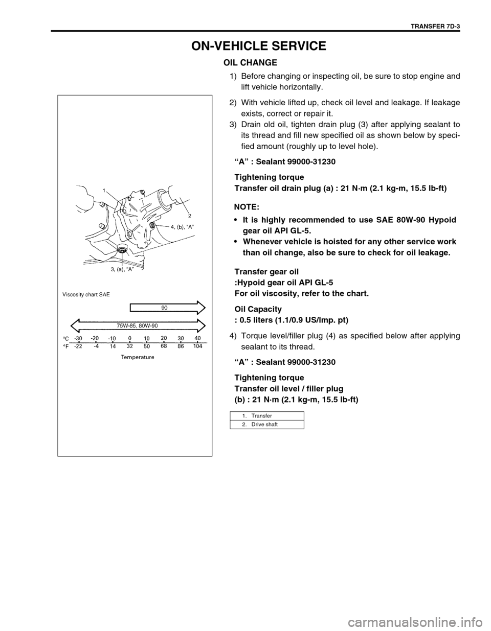
OIL CHANGE
1) Before changing or inspecting oil, be sure to stop engine and
lift vehicle horizontally.
2) With vehicle lifted up, check oil level and leakage. If leakage
exists, correct or repair it.
3) Drain old oil, tighten drain plug (3) after applying sealant to
its thread and fill new specified oil as shown below by speci-
fied amount (roughly up to level hole).
“A” : Sealant 99000-31230
Tightening torque
Transfer oil drain plug (a) : 21 N·m (2.1 kg-m, 15.5 lb-ft)
Transfer gear oil
:Hypoid gear oil API GL-5
For oil viscosity, refer to the chart.
Oil Capacity
: 0.5 liters (1.1/0.9 US/lmp. pt)
4) Torque level/filler plug (4) as specified below after applying
sealant to its thread.
“A” : Sealant 99000-31230
Tightening torque
Transfer oil level / filler plug
(b) : 21 N·m (2.1 kg-m, 15.5 lb-ft) NOTE:
It is highly recommended to use SAE 80W-90 Hypoid
gear oil API GL-5.
Whenever vehicle is hoisted for any other service work
than oil change, also be sure to check for oil leakage.
1. Transfer
2. Drive shaft
Page 219 of 447
TRANSFER 7D-21
Tighten mounting bolt and mounting bracket bolts and nuts
to specified torque.
Tightening torque
Transfer rear mounting bracket nuts
(a) : 50 N·m (5.0 kg-m, 36.5 lb-ft)
Transfer mounting bolt
(b) : 55 N·m (5.5 kg-m, 40.0 lb-ft)
Transfer rear mounting bracket No.2 bolts
(c) : 55 N·m (5.5 kg-m, 40.0 lb-ft)
Tighten transfer stiffener bolts (4) to specified torque.
Tightening torque
Transfer stiffener bolts (a) : 50 N·m (5.0 kg-m, 36.5 lb-ft)
Tighten exhaust pipe bolts.
Tightening torque
Exhaust pipe bolts
(a) : 50 N·m (5.0 kg-m, 36.5 lb-ft)
Install right side drive shaft, refer to Section 4A.
Install propeller shaft and tighten propeller shaft bolts and
center support bolts to specified torque (refer to Section 4B).
Fill gear oil to transfer as specified, refer to OIL CHANGE of
ON-VEHICLE SERVICE.
Check oil level and leakage.
(a)
(b)
(c)
1. Transmission
2. Transfer
3. Stiffener
1. Exhaust No.1 pipe
2. Exhaust No.2 pipe
1
(a)(a)2