Page 13 of 447

MANUAL TRANSMISSION 7A-13
INPUT & COUNTER SHAFT
1. Input shaft 13. Input shaft 5th gear 26. Countershaft
2. Oil seal
: Apply grease 99000-25010 to oil seal lip14. 5th gear spacer 27. Countershaft 1st gear
3. Input shaft right bearing 15. 5th gear needle bearing
(separated steel cage type)28. 1st gear synchronizer ring
4. Input shaft 3rd gear 16. 5th speed synchronizer ring 29. Low speed synchronizer spring
5. Needle bearing (resin cage type) 17. 5th synchronizer spring 30. Low speed sleeve & hub
5-1. Needle bearing (resin cage type) 18. 5th speed sleeve & hub 31. Low speed synchronizer key
6. High speed synchronizer ring 19. 5th synchronizer key 32. Circlip
7. High speed synchronizer spring 20. 5th synchronizer hub plate 33. 2nd gear synchronizer outer ring
8. High speed sleeve & hub 21. Circlip 34. Needle bearing
(separated steel cage type)
9. High speed synchronizer key 22. Reverse gear shaft 34-1. Needle bearing (steel cage type)
10. Circlip 23. Reverse idler gear 35. Countershaft 2nd gear
11. Input shaft 4th gear 24. Reverse shaft washer 36. Countershaft 3rd gear
12. Input shaft left bearing 25. Countershaft right bearing 37. 3rd & 4th gear spacer
Page 24 of 447

7A-24 MANUAL TRANSMISSION
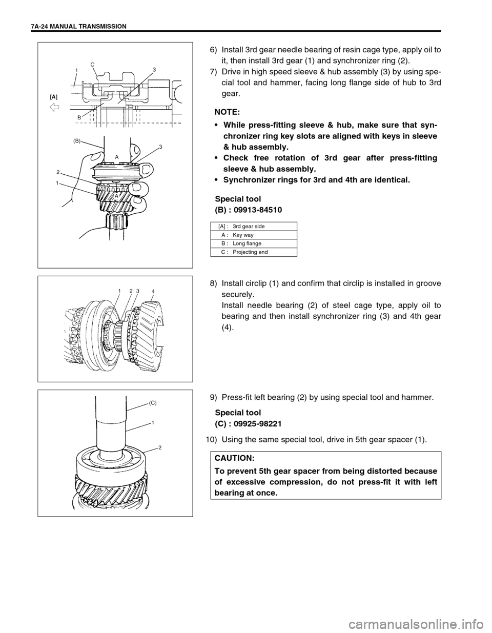
6) Install 3rd gear needle bearing of resin cage type, apply oil to
it, then install 3rd gear (1) and synchronizer ring (2).
7) Drive in high speed sleeve & hub assembly (3) by using spe-
cial tool and hammer, facing long flange side of hub to 3rd
gear.
Special tool
(B) : 09913-84510
8) Install circlip (1) and confirm that circlip is installed in groove
securely.
Install needle bearing (2) of steel cage type, apply oil to
bearing and then install synchronizer ring (3) and 4th gear
(4).
9) Press-fit left bearing (2) by using special tool and hammer.
Special tool
(C) : 09925-98221
10) Using the same special tool, drive in 5th gear spacer (1).NOTE:
While press-fitting sleeve & hub, make sure that syn-
chronizer ring key slots are aligned with keys in sleeve
& hub assembly.
Check free rotation of 3rd gear after press-fitting
sleeve & hub assembly.
Synchronizer rings for 3rd and 4th are identical.
[A] : 3rd gear side
A : Key way
B : Long flange
C : Projecting end
CAUTION:
To prevent 5th gear spacer from being distorted because
of excessive compression, do not press-fit it with left
bearing at once.
Page 27 of 447

MANUAL TRANSMISSION 7A-27
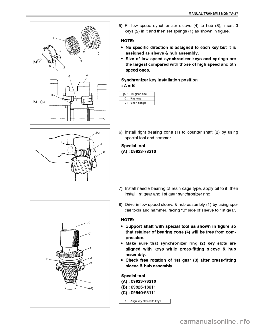
5) Fit low speed synchronizer sleeve (4) to hub (3), insert 3
keys (2) in it and then set springs (1) as shown in figure.
Synchronizer key installation position
: A = B
6) Install right bearing cone (1) to counter shaft (2) by using
special tool and hammer.
Special tool
(A) : 09923-78210
7) Install needle bearing of resin cage type, apply oil to it, then
install 1st gear and 1st gear synchronizer ring.
8) Drive in low speed sleeve & hub assembly (1) by using spe-
cial tools and hammer, facing “B” side of sleeve to 1st gear.
Special tool
(A) : 09923-78210
(B) : 09925-18011
(C) : 09940-53111 NOTE:
No specific direction is assigned to each key but it is
assigned as sleeve & hub assembly.
Size of low speed synchronizer keys and springs are
the largest compared with those of high speed and 5th
speed ones.
[A] : 1st gear side
C : Key way
D : Short flange
NOTE:
Support shaft with special tool as shown in figure so
that retainer of bearing cone (4) will be free from com-
pression.
Make sure that synchronizer ring (2) key slots are
aligned with keys while press-fitting sleeve & hub
assembly.
Check free rotation of 1st gear (3) after press-fitting
sleeve & hub assembly.
A : Align key slots with keys
Page 28 of 447
7A-28 MANUAL TRANSMISSION
9) Install circlip (1) and confirm that circlip is installed in groove
securely.
Install needle bearing (2) of separated steel cage type, apply
oil to bearing.
With synchronizer outer ring (3), center cone (4) & inner ring
(5) put together and installed to 2nd gear (6) as shown in fig-
ure.
10) Press-fit 3rd gear (2) and spacer (1) by using special tools
and press.
Special tool
(A) : 09923-78210
(D) : 09913-80112
11) Press-fit 4th gear (2) by using the same procedure as the
above.
12) Install left bearing cone (1) by using special tools and ham-
mer.
Special tool
(A) : 09923-78210
(E) : 09925-98221
[A] : SECTION A - A
CAUTION:
Press-fit 3rd gear and spacer first, and then 4th gear later
separately so that counter shaft will not be compressed
excessively.
NOTE:
For protection of right bearing cone (3), always support
shaft with special tool as illustrated.
Page 37 of 447

MANUAL TRANSMISSION 7A-37
8) Install needle bearing of separated steel cage type to input
shaft, apply oil then install 5th gear (1) and special tool to
stop shaft rotation.
Special tool
(B) : 09927-76010
9) Install new countershaft nut (2) and tighten it to specification.
Tightening torque
Countershaft nut (b) : 60 N·m (6.0 kg-m, 43.5 lb-ft)
10) Remove special tool, then caulk nut at C with caulking tool
and hammer.
11) Install synchronizer ring (2).
12) Fit 5th gear shift fork (1) to sleeve & hub assembly (3) and
install them into input shaft, shift shaft and shift guide shaft at
once aligning hub oil groove A with shaft mark B.
13) Drive in spring pin facing its slit A outward.
14) If equipped, install steel ball, tighten shift fork plug (3) to
which thread lock cement have been applied.
“A” : Thread lock 1322 99000-32110
Tightening torque
5th shift fork plug (c) : 10 N·m (1.0 kg-m, 7.5 lb-ft)
15) Fit hub plate (1) and fix it with circlip (2).
16) If equipped, install circlip (4) to the end of 5th & reverse gear
shift guide shaft.
NOTE:
Long flange of hub faces inward (gear side).
A : Oil groove (Align with B)
B : Punch mark
C : Caulking
CAUTION:
Coat shift fork plug with thread lock cement reason-
ably. If it is done to much, excess may interfere in ball
movement and cause hard shift to 5th speed.
Make sure circlip is installed in shaft groove securely.
A : Pin slit (Face outward)
Page 40 of 447
7A-40 MANUAL TRANSMISSION
REQUIRED SERVICE MATERIAL
SPECIAL TOOL
MaterialRecommended SUZUKI product
(Part Number)Use
Lithium grease SUZUKI SUPER GREASE A
(99000-25010) Oil seal lips
O-rings
Select lever boss
Select lever shaft bush
Gear shift control cable end
Sealant SUZUKI BOND NO.1215
(99000-31110) Oil drain plug and filler/level plug
Locating spring bolts
Mating surface of transmission case
Mating surface of side cover
Gear shift interlock bolt
5th to reverse interlock guide bolt
Thread lock cement THREAD LOCK 1322
(99000-32110) Reverse gear shift lever bolts
Oil gutter bolt
Shift fork plug
Reverse shaft bolt
Final gear bolts
09900-06107 09900-20606 09900-20701 09913-60910
Snap ring pliers
(Opening type)Dial gauge Magnetic stand Bearing puller
09913-75510 09913-80112 09913-84510 09922-85811
Bearing installer Bearing installer Bearing installer Spring pin remover
4.5 mm
Page 45 of 447

AUTOMATIC TRANSMISSION (4 A/T) 7B-3
GENERAL DESCRIPTION
This automatic transmission is a full automatic type with 3-speed plus overdrive (O/D).
The torque converter is a 3-element, 1-step and 2-phase type equipped with lock-up mechanism. The gear shift
device consists of 2 sets of planetary gear units, sets of 3 disc type clutches, 3sets of disc type brakes and one-
way clutch. The gear shift is done by selecting one of 6 positions (“P”, “R”, “N”, “D”, “2” and “L”) by means of the
select lever installed on the floor. On the shift knob, there is an overdrive (O/D) cut switch which allows shift-up
to the overdrive mode and shift-down from the overdrive mode.
1. Final gear 6. Overdrive brake (B0) 11. Oil strainer 16. Front clutch (C2)
2. Differential gear assembly 7. Direct clutch (C0) 12. Counter drive gear (Reduction gear) 17. Reverse brake (B2)
3. Parking gear 8. Rear planetary gear 13. Oil pump 18. Rear clutch (C1)
4. Counter driven gear (Reduction gear) 9. Front planetary gear 14. Input shaft 19. Differential drive pinion shaft
5. 1st and 2nd brake (B1) 10. Valve body assembly 15. Torque converter
Page 46 of 447

7B-4 AUTOMATIC TRANSMISSION (4 A/T)
Item Specifications
Torque
converterType
Stall torque ratio3-element, 1-step, 2-phase type
1.65 –1.85
Oil pumpType
Drive systemInternal gear type oil pump
Engine driven
Gear
change
deviceType Forward 4-step, reverse 1-step planetary gear type
Shift position“P” range Gear in neutral, output shaft fixed, engine start
“R” range Reverse
“N” range Gear in neutral, engine start
“D” range
(O/D ON)Forward 1st ↔
2nd ↔
3rd ↔
4th (O/D)
automatic gear change
“D” range
(O/D OFF)Forward 1st ↔
2nd ↔
3rd ←
4th
automatic gear change
“2” range Forward 1st ↔
2nd ←
3rd automatic gear change
“L” range Forward 1st ←
2nd reduction, and fixed at 1st gear
Gear
ratio1st 2.962
2nd 1.515 Number of teeth Front sun gear : 34
Rear sun gear : 21
Front pinion gear : 16
Rear pinion gear : 19
Front internal gear : 66
Rear internal gear : 59 3rd 1.000
4th
(overdrive gear)0.737
Reverse
(reverse gear2.809
Control elementsWet type multi-disc clutch ... 3 sets
One-way clutch ... 1 set
Wet type multi-disc brake ... 3 sets
Reduction gear ratio 1.209
Final gear ratio
(Differential)3.578 (for 2WD vehicle), 3.894 (for 4WD vehicle)
Lubrication Lubrication system Force feed system by oil pump
Cooling Cooling system Water-cooled
Fluid used
Equivalent of DEXRON
-III or DEXRON-IIE