Page 216 of 447

7D-18 TRANSFER
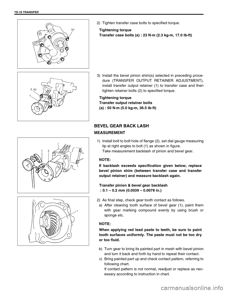
2) Tighten transfer case bolts to specified torque.
Tightening torque
Transfer case bolts (a) : 23 N·m (2.3 kg-m, 17.0 lb-ft)
3) Install the bevel pinion shim(s) selected in preceding proce-
dure (TRANSFER OUTPUT RETAINER ADJUSTMENT),
install transfer output retainer (1) to transfer case and then
tighten retainer bolts (2) to specified torque.
Tightening torque
Transfer output retainer bolts
(a) : 50 N·m (5.0 kg-m, 36.5 lb-ft)
BEVEL GEAR BACK LASH
MEASUREMENT
1) Install bolt to bolt hole of flange (2), set dial gauge measuring
tip at right angles to bolt (1) as shown in figure.
Take measurement backlash of pinion and bevel gear.
Transfer pinion & bevel gear backlash
: 0.1 – 0.2 mm (0.0039 – 0.0078 in.)
2) As final step, check gear tooth contact as follows.
a) After cleaning tooth surface of bevel gear (1), paint them
with gear marking compound evenly by using brush or
sponge etc.
b) Turn gear to bring its painted part in mesh with bevel pinion
and turn it back and forth by hand to repeat their contact.
c) Bring painted part up and check contact pattern, referring to
following chart.
If contact pattern is not normal, readjust or replace as nec-
essary according to instruction in chart.
NOTE:
If backlash exceeds specification given below, replace
bevel pinion shim (between transfer case and transfer
output retainer) and measure backlash again.
NOTE:
When applying red lead paste to teeth, be sure to paint
tooth surfaces uniformly. The paste must not be too dry
or too fluid.
Page 218 of 447

7D-20 TRANSFER
UNIT INSTALLATION
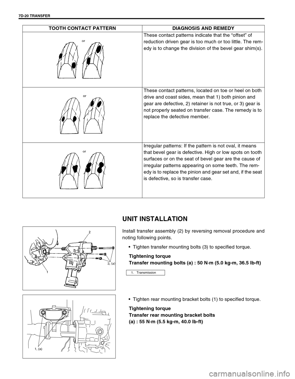
Install transfer assembly (2) by reversing removal procedure and
noting following points.
Tighten transfer mounting bolts (3) to specified torque.
Tightening torque
Transfer mounting bolts (a) : 50 N·m (5.0 kg-m, 36.5 lb-ft)
Tighten rear mounting bracket bolts (1) to specified torque.
Tightening torque
Transfer rear mounting bracket bolts
(a) : 55 N·m (5.5 kg-m, 40.0 lb-ft)These contact patterns indicate that the “offset” of
reduction driven gear is too much or too little. The rem-
edy is to change the division of the bevel gear shim(s).
These contact patterns, located on toe or heel on both
drive and coast sides, mean that 1) both pinion and
gear are defective, 2) retainer is not true, or 3) gear is
not properly seated on transfer case. The remedy is to
replace the defective member.
Irregular patterns: If the pattern is not oval, it means
that bevel gear is defective. High or low spots on tooth
surfaces or on the seat of bevel gear are the cause of
irregular patterns appearing on some teeth. The rem-
edy is to replace the pinion and gear set and, if the seat
is defective, so is transfer case. TOOTH CONTACT PATTERN DIAGNOSIS AND REMEDY
1. Transmission
1, (a)
Page 220 of 447
7D-22 TRANSFER
TIGHTENING TORQUE SPECIFICATION
REQUIRED SERVICE MATERIAL
SPECIAL TOOL
Fastening partTightening torque
Nm kg-m lb-ft
Transfer oil level/filler and drain plugs 21 2.1 15.5
Transfer bevel gear nut 150 15.0 108.5
Transfer case bolts 23 2.3 17.0
Transfer output retainer bolts 50 5.0 36.5
Transfer mounting bolts 50 5.0 36.5
Transfer rear mounting bracket bolts 55 5.5 40.0
Transfer rear mounting bracket nuts 50 5.5 36.5
Transfer mounting bolt 55 5.5 40.0
Transfer rear mounting bracket No.2 bolts 55 5.5 40.0
Transfer stiffener bolts 50 5.0 36.5
Exhaust pipe bolts 50 5.0 36.5
MaterialRecommended SUZUKI products
(Part Number)Use
Lithium grease SUZUKI SUPER GREASE A
(99000-25010)Oil seal lips
Sealant SUZUKI BOND NO. 1216B
(99000-31230)Oil drain plug
Oil level plug
Mating surface of transfer case
09913-65135 09925-58210 09941-54911 09924-84510-005
Bearing puller Oil seal installer Bearing outer race
removerBearing installer attach-
ment
Page 221 of 447
TRANSFER 7D-23
09913-75821 09930-40113 09913-50121 09913-75810
Bearing installer attach-
mentRotor holder Oil seal remover Bearing installer
09945-16070 09952-76011 09922-76140 09922-76150
Retainer ring installer set Snap ring pliers
(closing type)Bevel pinion shaft Bevel pinion nut
09922-76340 09922-76430 09951-16090
Rear collar Front collar Oil seal installer
Page 225 of 447
REAR DIFFERENTIAL 7F-3
DIAGNOSIS
Condition Possible Cause Correction
Gear noise
Deteriorated or water mixed lubricant Repair and replenish.
Inadequate or insufficient lubricant Repair and replenish.
Maladjusted backlash between bevel pinion
and gearAdjust and prescribed.
Improper tooth contact in the mesh between
bevel pinion and gearAdjust or replace.
Loose bevel gear securing bolts Replace or retighten.
Damaged side gear(s) or side pinion(s) Replace.
Bearing noise
(Constant noise) Deteriorated or water mixed
lubricantRepair or replenish.
(Constant noise) Inadequate or insufficient
lubricantRepair or replenish.
(Noise while coasting) Damaged bearing(s) of
bevel pinionReplace.
(Noise while turning) Damaged differential side
bearing(s)Replace.
Oil leakage
Clogged breather plug Clean.
Worn or damaged oil seal Replace.
Excessive oil Adjust oil level.
Page 227 of 447

REAR DIFFERENTIAL 7F-5
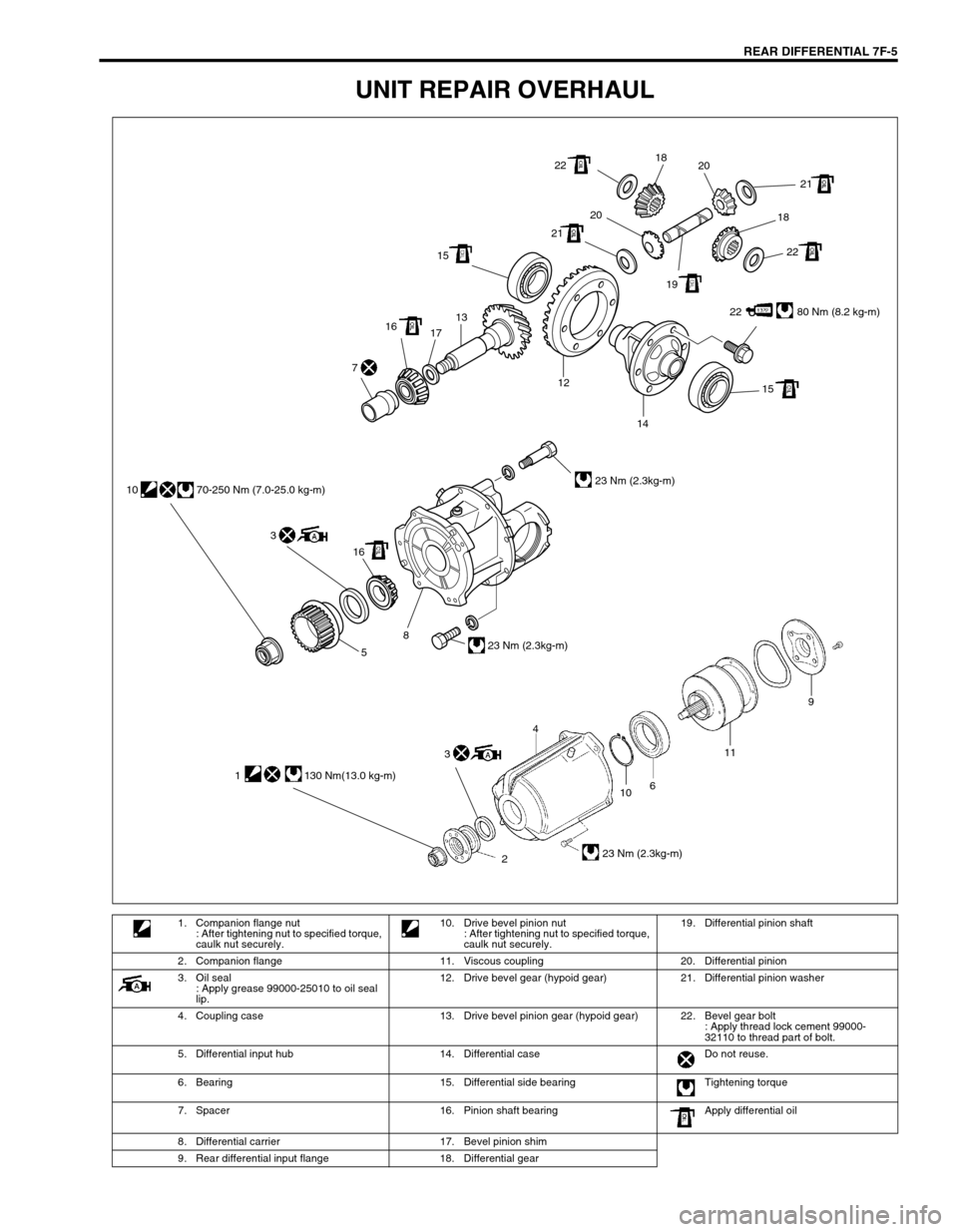
UNIT REPAIR OVERHAUL
22 80 Nm (8.2 kg-m) 1513
17 16
15 12
14 7
22
22 2121
2020
1918 18
16 3 10 70-250 Nm (7.0-25.0 kg-m)
23 Nm (2.3kg-m)
23 Nm (2.3kg-m)
8
5
10
2611
23 Nm (2.3kg-m)
9
4
1 130 Nm(13.0 kg-m)
3
1. Companion flange nut
: After tightening nut to specified torque,
caulk nut securely.10. Drive bevel pinion nut
: After tightening nut to specified torque,
caulk nut securely.19. Differential pinion shaft
2. Companion flange 11. Viscous coupling 20. Differential pinion
3. Oil seal
: Apply grease 99000-25010 to oil seal
lip.12. Drive bevel gear (hypoid gear) 21. Differential pinion washer
4. Coupling case 13. Drive bevel pinion gear (hypoid gear) 22. Bevel gear bolt
: Apply thread lock cement 99000-
32110 to thread part of bolt.
5. Differential input hub 14. Differential case Do not reuse.
6. Bearing 15. Differential side bearing Tightening torque
7. Spacer 16. Pinion shaft bearing Apply differential oil
8. Differential carrier 17. Bevel pinion shim
9. Rear differential input flange 18. Differential gear
Page 228 of 447
7F-6 REAR DIFFERENTIAL
DIFFERENTIAL UNIT
DISMOUNTING
1) Hoist vehicle and remove wheels.
2) Drain oil from rear differential. (Refer to “OIL CHANGE” in
this section.)
3) Remove brake drum and disconnect parking brake cable
from brake back plate.
4) Remove axle shafts, refer to “REAR AXLE SHAFT AND
WHEEL BEARING REMOVAL” in Section 3E.
5) Before removing propeller shaft, give match marks (1) on
joint flange and propeller shaft as shown.
6) Remove differential carrier bolts and differential assembly
with viscous coupling case.
1. Drain plug
2. Level plug
1
Page 229 of 447

REAR DIFFERENTIAL 7F-7
REMOUNTING
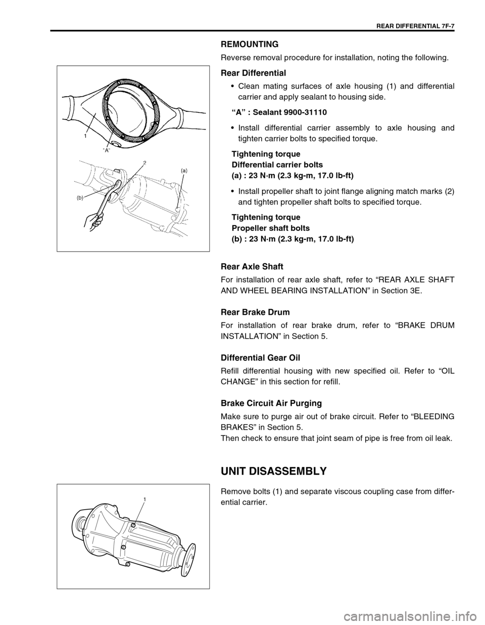
Reverse removal procedure for installation, noting the following.
Rear Differential
Clean mating surfaces of axle housing (1) and differential
carrier and apply sealant to housing side.
“A” : Sealant 9900-31110
Install differential carrier assembly to axle housing and
tighten carrier bolts to specified torque.
Tightening torque
Differential carrier bolts
(a) : 23 N·m (2.3 kg-m, 17.0 lb-ft)
Install propeller shaft to joint flange aligning match marks (2)
and tighten propeller shaft bolts to specified torque.
Tightening torque
Propeller shaft bolts
(b) : 23 N·m (2.3 kg-m, 17.0 lb-ft)
Rear Axle Shaft
For installation of rear axle shaft, refer to “REAR AXLE SHAFT
AND WHEEL BEARING INSTALLATION” in Section 3E.
Rear Brake Drum
For installation of rear brake drum, refer to “BRAKE DRUM
INSTALLATION” in Section 5.
Differential Gear Oil
Refill differential housing with new specified oil. Refer to “OIL
CHANGE” in this section for refill.
Brake Circuit Air Purging
Make sure to purge air out of brake circuit. Refer to “BLEEDING
BRAKES” in Section 5.
Then check to ensure that joint seam of pipe is free from oil leak.
UNIT DISASSEMBLY
Remove bolts (1) and separate viscous coupling case from differ-
ential carrier.1