Page 195 of 447
CLUTCH 7C-13
3) Apply grease to No.2 bush (1) inside and press-fit it by using
the same special tool as in removal.
“A” : Grease 99000-25010
Special tool
(C) : 09922-46010
4) Coat grease to shaft seal (2) lip and then install it till it is flush
with case surface. Use special tool for this installation and
face seal lip downward (inside).
“A” : Grease 99000-25010
Special tool
(D) : 09925-98221
5) Caulk seal at A by using caulking tool and hammer.
6) Hook return spring.
7) Apply grease to release bearing (1) inside and release shaft
arm (2), then set bearing.
“A” : Grease 99000-25010
8) Apply small amount of grease to input shaft (3) spline (0.3 g)
and front end (0.15 g) as well.
“B” : Grease 99000-25210
9) Set release lever to release shaft aligning their punch marks
(1), then tighten bolt.
Tightening torque
Release lever bolt (a) : 23 N·m (2.3 kg-m, 16.5 lb-ft)
Page 196 of 447
7C-14 CLUTCH
TIGHTENING TORQUE SPECIFICATION
REQUIRED SERVICE MATERIAL
SPECIAL TOOL
Fastening partTightening torque
Nm kg-m lb-ft
Flywheel bolts 70 7.0 50.5
Clutch cover bolts 23 2.3 16.5
Release lever bolt 23 2.3 16.5
MaterialRecommended SUZUKI product
(Part Number)Use
Lithium grease SUZUKI SUPER GREASE A
(99000-25010)Cable end hook and joint pin.
Release shaft bushes and seal.
Release shaft arm.
Release bearing inside.
SUZUKI SUPER GREASE I
(99000-25210)Input shaft spline and front end.
09921-26020 09922-46010 09923-36320 09923-46020
Bearing remover Bush remover Clutch center guide Joint pipe
09923-46030 09924-17810 09925-98210 09925-98221
Joint pipe Flywheel holder Input shaft bearing
installerBearing installer
Page 200 of 447
7D-2 TRANSFER
GENERAL DESCRIPTION
The transfer consists of parts as shown in figure.
DIAGNOSIS
1. Intermediate shaft 6. Shim 11. Transfer output retainer
2. Left case 7. Reduction driven gear 12. Flange
3. Reduction drive gear 8. Bevel gear✱
:Forward
4. Circlip 9. Bevel pinion shaft
5. Right case 10. Pinion shaft spacer
Condition Possible Cause Correction
Noise
Inadequate or insufficient lubricant Replenish.
Damaged or worn bearing(s) Replace.
Damaged or worn gear(s) Replace.
Damaged or worn chamfered tooth on sleeve or
gearReplace.
Preload of taper roller bearing is reduced Adjust.
Page 202 of 447

7D-4 TRANSFER
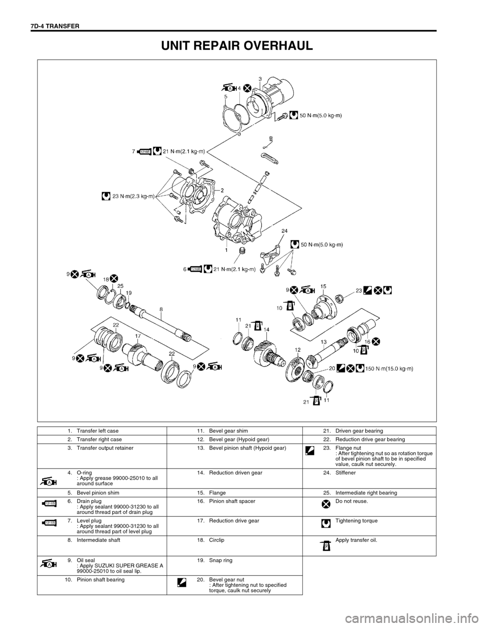
UNIT REPAIR OVERHAUL
1. Transfer left case 11. Bevel gear shim 21. Driven gear bearing
2. Transfer right case 12. Bevel gear (Hypoid gear) 22. Reduction drive gear bearing
3. Transfer output retainer 13. Bevel pinion shaft (Hypoid gear) 23. Flange nut
: After tightening nut so as rotation torque
of bevel pinion shaft to be in specified
value, caulk nut securely.
4. O-ring
: Apply grease 99000-25010 to all
around surface14. Reduction driven gear 24. Stiffener
5. Bevel pinion shim 15. Flange 25. Intermediate right bearing
6. Drain plug
: Apply sealant 99000-31230 to all
around thread part of drain plug16. Pinion shaft spacer Do not reuse.
7. Level plug
: Apply sealant 99000-31230 to all
around thread part of level plug17. Reduction drive gear Tightening torque
8. Intermediate shaft 18. Circlip Apply transfer oil.
9. Oil seal
: Apply SUZUKI SUPER GREASE A
99000-25010 to oil seal lip.19. Snap ring
10. Pinion shaft bearing 20. Bevel gear nut
: After tightening nut to specified
torque, caulk nut securely
Page 204 of 447
7D-6 TRANSFER
10) Remove mounting (1) and mounting bracket (2) from trans-
fer assembly.
UNIT DISASSEMBLY
TRANSFER ASSEMBLY
1) Remove retainer bolts (2) and remove transfer output
retainer (1).
2) Remove transfer case bolts.
3) Separate right case with intermediate shaft from left case by
tapping with plastic hammer.
4) Remove reduction drive gear (1) from left case by tapping
with plastic hammer.
1
2
2. Bearing
Page 205 of 447
TRANSFER 7D-7
5) Remove drive gear bearings (1) (right and left) from reduc-
tion drive gear by using bearing puller (2).
REDUCTION DRIVEN GEAR
1) Drive out left side driven gear bearing by using special tool.
Special tool
(A) : 09913-65135
2) Drive out right side driven gear bearing by using bearing
puller, press and special tool.
Special tool
(A) : 09925-58210
3) Uncaulk bevel gear nut, remove bevel gear nut while holding
bevel gear with soft jawed vise.
4) Drive out bevel gear (1) by using special tool.
Special tool
(A) : 09913-65135
Page 206 of 447
7D-8 TRANSFER
5) Remove driven gear bearing outer race from left case (1) by
using special tool.
Special tool
(A) : 09941-54911
6) Remove driven gear bearing outer race from right case (1)
by using special tool.
Special tool
(A) : 09941-54911
INTERMEDIATE SHAFT
1) Remove reduction drive oil seal and snap ring, and then
drive out intermediate shaft.
2) Drive out intermediate right bearing (1) from intermediate
shaft by using bearing puller and press.
3) Remove intermediate center oil seals (1) by using press and
special tools.
Special tool
(A) : 09924-84510-005
(B) : 09913-75821
Page 207 of 447
TRANSFER 7D-9
TRANSFER OUTPUT RETAINER
1) Uncaulk flange nut.
2) Remove flange nut while holding flange (2) by using special
tool.
Special tool
(A) : 09930-40113
3) Remove flange (1) by special tool.
Special tool
(A) : 09913-65135
4) Drive out bevel pinion shaft from transfer output retainer by
tapping with plastic hammer.
5) Drive out pinion spacer from bevel pinion shaft.
6) Drive out pinion shaft bearing (2) from bevel pinion shaft (1)
by using press.
7) Remove pinion shaft oil seal (1) by using special tool.
Special tool
(A) : 09913-50121
1. Power wrench
3. Bearing puller