Page 258 of 447

8-14 BODY ELECTRICAL SYSTEM
REAR FOG LIGHT (IF EQUIPPED)
REAR FOG LIGHT SWITCH
INSPECTION
Check for continuity between terminals. Hold the switch button (ON or OFF) pushed in during checking switch.
IGNITION SWITCH
ON-VEHICLE INSPECTION
1) Disconnect negative cable at battery.
2) Remove steering column hole cover.
3) Remove steering column upper and lower cover.
4) Disconnect main harness couplers from ignition switch.
5) Check for continuity between terminals at each switch posi-
tion as shown below. If check result is not as specified,
replace.
REMOVAL
1) Disconnect negative cable at battery.
2) Remove steering column hole cover.
3) Remove steering column upper and lower cover.
4) Disconnect main harness couplers from ignition switch (1).
5) Remove ignition switch (1) from key cylinder (2).
INSTALLATION
Reverse removal procedure for installation.
RR
FOG SW
OFF SWTERMINAL
FREEFREE
PUSH
FREE
PUSH PUSHBE D AC F
NOTE:
Rear fog light lights up only when headlight (low or high beams) or front fog light switch (if equipped)
is ON. Rear fog lights turns OFF automatically when headlight or front fog light switch is turned OFF.
ST+B1
+B2
ACCIG2
IG1K1K2
+B1+B2
ACC IG1IG2STK1
K2
LOCK
ACC
ONSTKEY
DIRECTION
12
Position Key
OUT
LOCK
ACC
ON
START IN+B1 +B2 +ACC IG1 IG2 ST K1 K2 Terminal
Page 260 of 447

8-16 BODY ELECTRICAL SYSTEM
REMOVAL
1) Disconnect negative cable at battery.
2) Loosen steering column mounting nuts. Refer to Section 3C.
3) Remove meter cluster panel (1).
4) Disconnect all couplers from combination meter, then
remove combination meter (2).
INSTALLATION
Reverse removal procedure for installation.
INSPECTION
Check printed plate (1) visually for scratch, crack and discolora-
tion.
If any of such faulty conditions is found, replace the printed plate
(1).
FUEL METER AND FUEL LEVEL SENSOR
(GAUGE UNIT)
FUEL LEVEL METER
INSPECTION
Operation check
1) Remove combination meter. Refer to “COMBINATION
METER”.
2) Remove “YEL/RED” wire terminal from combination meter
connector and reconnect combination connectors to combi-
nation meter.
3) Turn ignition switch ON, and check that pointer (2) of fuel
meter indicates “E”.
4) Turn ignition switch OFF.
5) Short “YEL/RED” wire terminal to body ground through a 3.4
W bulb (1) as shown in figure.
6) Turn ignition switch ON, and check that bulb light up and
pointer (2) of meter moves from “E” to “F”.
If check result is not satisfied, replace.
1
2
YEL/REDF
E
2 1
Page 261 of 447

BODY ELECTRICAL SYSTEM 8-17
FUEL LEVEL SENSOR (GAUGE UNIT)
REMOVAL
Remove fuel pump assembly (1) referring to Section 6C.
INSTALLATION
Install fuel pump assembly (1) referring to Section 6C.
INSPECTION
Check that resistance between terminals “a” and “b” of fuel
level sensor changes with change of float position.
Check resistance between terminals “a” and “b” in each float
position below.
If the measured value is out of specification, replace.
Fuel level sensor specification
SPEED METER AND VSS
VSS
REMOVAL AND INSTALLATION
Refer to “VSS” in Section 6E1.
ENGINE COOLANT TEMPERATURE (ECT)
METER AND SENSOR
ENGINE COOLANT TEMPERATURE (ECT) METER
INSPECTION
Operation check
1) Remove combination meter. Refer to “COMBINATION
METER”.
2) Remove “YEL/GRN” wire terminal from combination meter
connector and reconnect combination connectors to combi-
nation meter.
3) Turn ignition switch ON, and check that pointer (2) of ECT
meter indicates “C” as shown in figure.
4) Ignition switch OFF.
5) Short “YEL/GRN” wire terminal to body ground through a 3.4
W bulb (1) as shown in figure.
6) Turn ignition switch ON, and check that bulb light up and
pointer (2) of meter moves from “C” to “H”.
If check result is not satisfied, replace.Float Position Resistance (Ω
)
Full Upper “c”59.6 mm (2.35 in.) 2 - 4
Middle (1/2) “d”121.6 mm (4.79 in.) 29.5 - 35.5
Full Lower “e”202.3 mm (7.96 in.) 119 - 121
“a”“b”
1
“c”
“d”
“e”
YEL/GRNC
H1
2
Page 262 of 447
8-18 BODY ELECTRICAL SYSTEM
ECT SENSOR
REMOVAL, INSTALLATION AND INSPECTION
Refer to “ECT SENSOR” in Section 6E1.
OIL PRESSURE WARNING LIGHT
OIL PRESSURE SWITCH
ON-VEHICLE INSPECTION
1) Disconnect oil pressure switch (1) lead wire.
2) Check for continuity between oil pressure switch terminal (2)
and cylinder block (3) as shown in figure.
If not, replace oil pressure switch (1).
Oil pressure switch specification
During engine running : No continuity
At engine stop : Continuity
REMOVAL AND INSTALLATION
Refer to “OIL PRESSURE CHECK” in Section 6A1.
BRAKE FLUID LEVEL AND PARKING BRAKE
WARNING LIGHT
BRAKE FLUID LEVEL SWITCH
INSPECTION
Check for continuity between terminals of brake fluid level switch
coupler.
If found defective, replace switch.
Brake fluid level switch specification
OFF position (float up) : No continuity
ON position (float down) : Continuity
Page 263 of 447
BODY ELECTRICAL SYSTEM 8-19
PARKING BRAKE SWITCH
INSPECTION
Check for continuity between parking brake switch terminal and
body ground as shown in figure.
If found defective, replace switch.
Parking brake switch specification
OFF position (parking brake released) (1) :
No continuity
ON position (parking brake lever pulled up) (2) :
Continuity
REAR WINDOW DEFOGGER
DEFOGGER SWITCH
INSPECTION
Check for continuity between terminals at each switch position as
shown below. If check result is not satisfied, replace.
DEFOGGER WIRE
INSPECTION
SwitchPositionTerminal
ON (PUSH IN)IG LOAD E IL ILE
OFF
NOTE:
When cleaning rear window glass, use a dry cloth to
wipe it along heat wire (1) direction.
When cleaning glass, do not use detergent or abra-
sive-containing glass cleaner.
When measuring wire voltage, use a tester with nega-
tive probe (2) wrapped with a tin foil (3) which should
be held down on wire by finger pressure.
Page 265 of 447
BODY ELECTRICAL SYSTEM 8-21
WIPERS AND WASHERS
COMPONENTS
FRONT WIPER AND WASHER SWITCH
REMOVAL AND INSTALLATION
Refer to “CONTACT COIL AND COMBINATION SWITCH
ASSEMBLY” in Section 3C.
[A] : RH steering vehicle 3. Wiper motor 7. Washer hose
[B] : LH steering vehicle 4. Washer pump (for front washer) 8. Washer nozzle
1. Wiper blade 5. Washer pump (for rear washer) 9. Wiper link
2. Wiper arm 6. Washer tank
Page 266 of 447

8-22 BODY ELECTRICAL SYSTEM
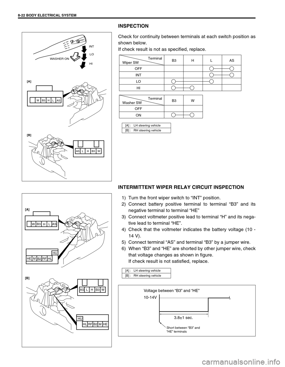
INSPECTION
Check for continuity between terminals at each switch position as
shown below.
If check result is not as specified, replace.
INTERMITTENT WIPER RELAY CIRCUIT INSPECTION
1) Turn the front wiper switch to “INT” position.
2) Connect battery positive terminal to terminal “B3” and its
negative terminal to terminal “HE”
3) Connect voltmeter positive lead to terminal “H” and its nega-
tive lead to terminal “HE”.
4) Check that the voltmeter indicates the battery voltage (10 -
14 V).
5) Connect terminal “AS” and terminal “B3” by a jumper wire.
6) When “B3” and “HE” are shorted by other jumper wire, check
that voltage changes as shown in figure.
If check result is not satisfied, replace.
[A] : LH steering vehicle
[B] : RH steering vehicle
INT
WASHER ONLO
[A]
[B]HI
AS AS
L L
H H
B3 B3
W W
HI LO INT OFF
PULL
Terminal
Wiper SW
OFF
INT
LOB3 H L AS
HI
Terminal
Washer SW
OFF
ONB3 W
[A] : LH steering vehicle
[B] : RH steering vehicle
AS L H B3 W
HU
HL RF B2 M HE
AS
L
H B3
W
HU
HL RF
B2 M HE [A]
[B]
10-14V Voltage between “B3” and “HE”
3.8±1 sec.
Short between “B3” and
“HE” terminals
Page 267 of 447

BODY ELECTRICAL SYSTEM 8-23
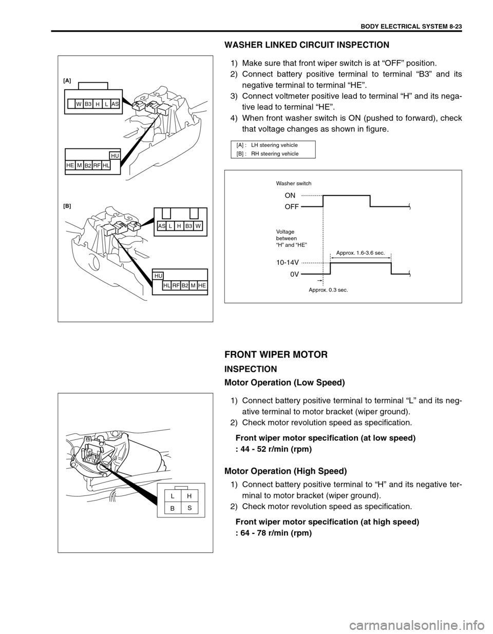
WASHER LINKED CIRCUIT INSPECTION
1) Make sure that front wiper switch is at “OFF” position.
2) Connect battery positive terminal to terminal “B3” and its
negative terminal to terminal “HE”.
3) Connect voltmeter positive lead to terminal “H” and its nega-
tive lead to terminal “HE”.
4) When front washer switch is ON (pushed to forward), check
that voltage changes as shown in figure.
FRONT WIPER MOTOR
INSPECTION
Motor Operation (Low Speed)
1) Connect battery positive terminal to terminal “L” and its neg-
ative terminal to motor bracket (wiper ground).
2) Check motor revolution speed as specification.
Front wiper motor specification (at low speed)
: 44 - 52 r/min (rpm)
Motor Operation (High Speed)
1) Connect battery positive terminal to “H” and its negative ter-
minal to motor bracket (wiper ground).
2) Check motor revolution speed as specification.
Front wiper motor specification (at high speed)
: 64 - 78 r/min (rpm)
[A] : LH steering vehicle
[B] : RH steering vehicle
AS L H B3 W
HU
HL RF B2 M HE
HU
HL RF
B2 M HE [A]
[B]
AS
L
H B3
W
10-14V
Washer switch
Voltage
between
“H” and “HE”
0V ON
OFF
Approx. 0.3 sec.Approx. 1.6-3.6 sec.
LH
S
B