Page 6 of 447
7A-6 MANUAL TRANSMISSION
OIL CHANGE
1) Before changing or inspecting oil, be sure to stop engine and
lift vehicle horizontally.
2) With vehicle lifted up, check oil level and leakage.
If leakage exists, correct it.
3) Drain old oil and fill new specified oil by specified amount (up
to level hole).
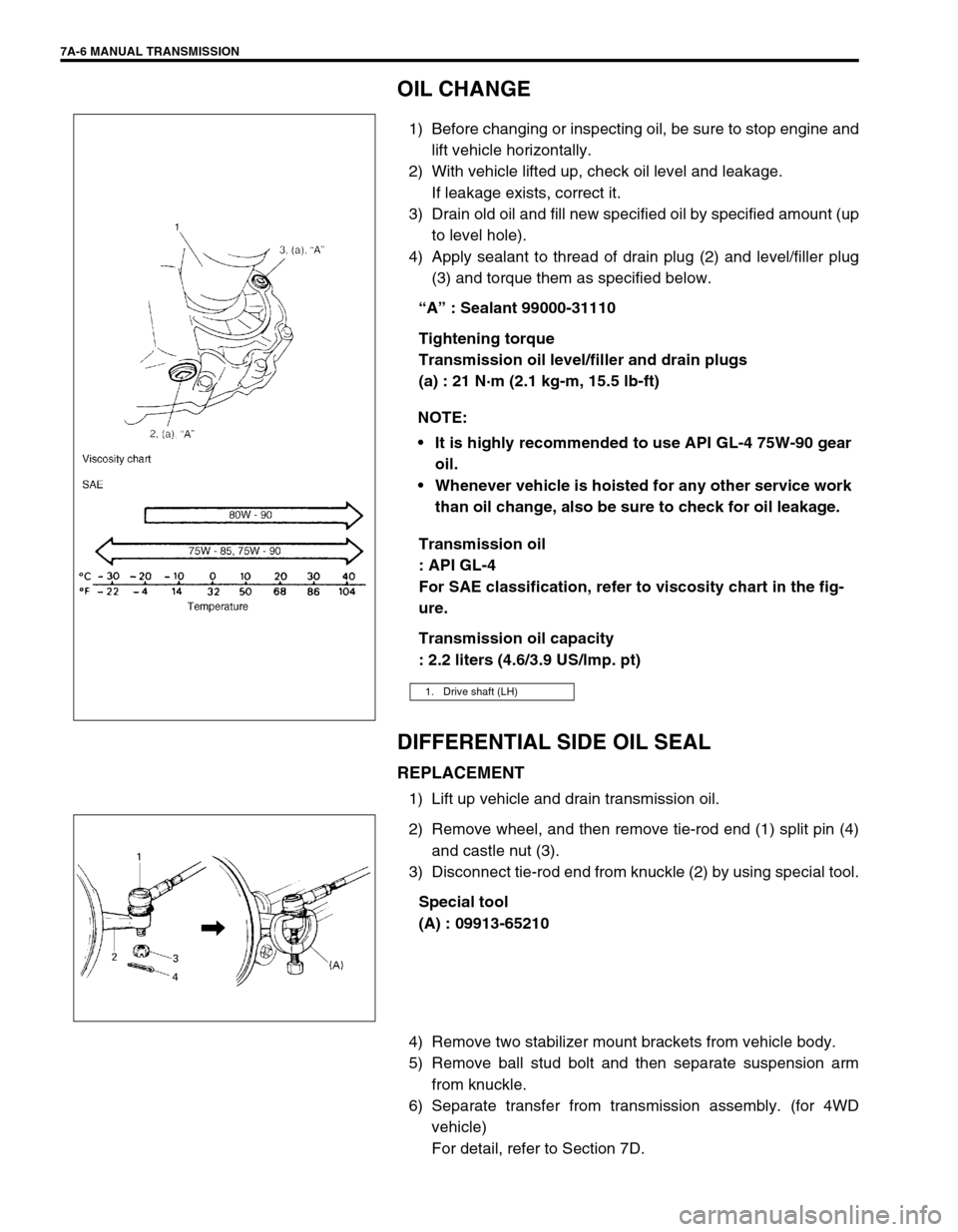
4) Apply sealant to thread of drain plug (2) and level/filler plug
(3) and torque them as specified below.
“A” : Sealant 99000-31110
Tightening torque
Transmission oil level/filler and drain plugs
(a) : 21 N·m (2.1 kg-m, 15.5 lb-ft)
Transmission oil
: API GL-4
For SAE classification, refer to viscosity chart in the fig-
ure.
Transmission oil capacity
: 2.2 liters (4.6/3.9 US/lmp. pt)
DIFFERENTIAL SIDE OIL SEAL
REPLACEMENT
1) Lift up vehicle and drain transmission oil.
2) Remove wheel, and then remove tie-rod end (1) split pin (4)
and castle nut (3).
3) Disconnect tie-rod end from knuckle (2) by using special tool.
Special tool
(A) : 09913-65210
4) Remove two stabilizer mount brackets from vehicle body.
5) Remove ball stud bolt and then separate suspension arm
from knuckle.
6) Separate transfer from transmission assembly. (for 4WD
vehicle)
For detail, refer to Section 7D. NOTE:
It is highly recommended to use API GL-4 75W-90 gear
oil.
Whenever vehicle is hoisted for any other service work
than oil change, also be sure to check for oil leakage.
1. Drive shaft (LH)
Page 7 of 447
MANUAL TRANSMISSION 7A-7
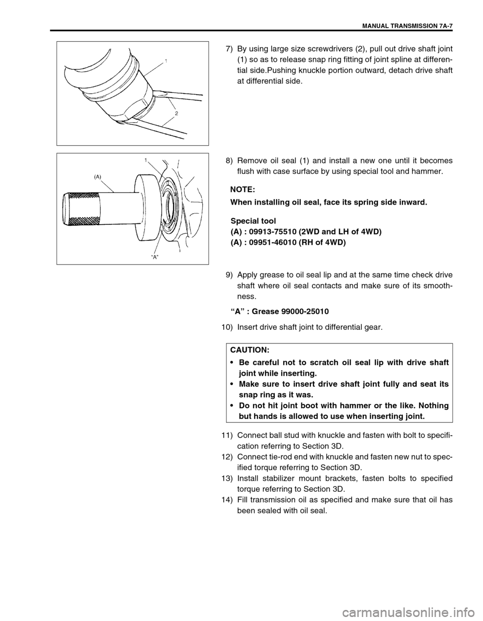
7) By using large size screwdrivers (2), pull out drive shaft joint
(1) so as to release snap ring fitting of joint spline at differen-
tial side.Pushing knuckle portion outward, detach drive shaft
at differential side.
8) Remove oil seal (1) and install a new one until it becomes
flush with case surface by using special tool and hammer.
Special tool
(A) : 09913-75510 (2WD and LH of 4WD)
(A) : 09951-46010 (RH of 4WD)
9) Apply grease to oil seal lip and at the same time check drive
shaft where oil seal contacts and make sure of its smooth-
ness.
“A” : Grease 99000-25010
10) Insert drive shaft joint to differential gear.
11) Connect ball stud with knuckle and fasten with bolt to specifi-
cation referring to Section 3D.
12) Connect tie-rod end with knuckle and fasten new nut to spec-
ified torque referring to Section 3D.
13) Install stabilizer mount brackets, fasten bolts to specified
torque referring to Section 3D.
14) Fill transmission oil as specified and make sure that oil has
been sealed with oil seal.
NOTE:
When installing oil seal, face its spring side inward.
CAUTION:
Be careful not to scratch oil seal lip with drive shaft
joint while inserting.
Make sure to insert drive shaft joint fully and seat its
snap ring as it was.
Do not hit joint boot with hammer or the like. Nothing
but hands is allowed to use when inserting joint.
Page 17 of 447
MANUAL TRANSMISSION 7A-17
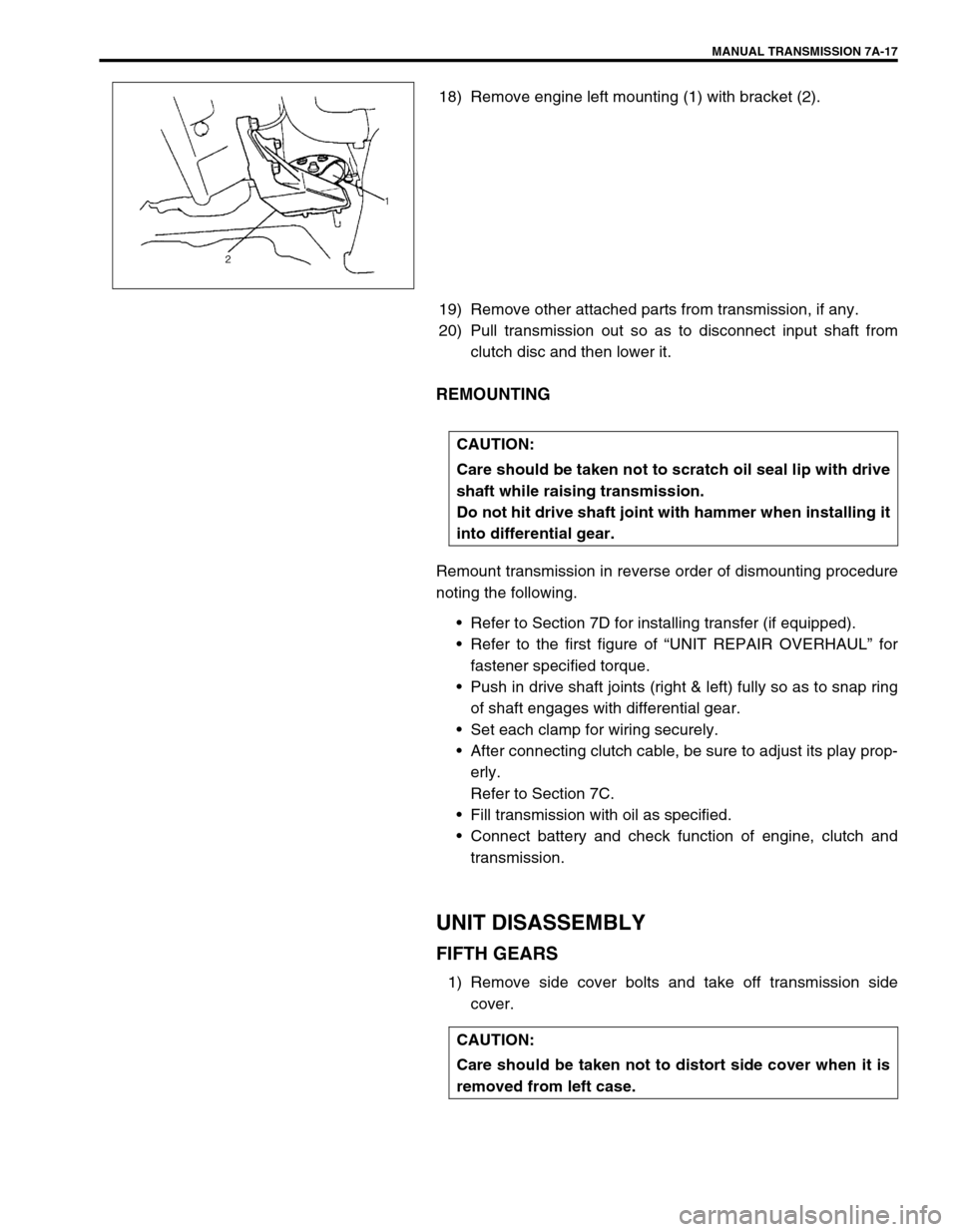
18) Remove engine left mounting (1) with bracket (2).
19) Remove other attached parts from transmission, if any.
20) Pull transmission out so as to disconnect input shaft from
clutch disc and then lower it.
REMOUNTING
Remount transmission in reverse order of dismounting procedure
noting the following.
Refer to Section 7D for installing transfer (if equipped).
Refer to the first figure of “UNIT REPAIR OVERHAUL” for
fastener specified torque.
Push in drive shaft joints (right & left) fully so as to snap ring
of shaft engages with differential gear.
Set each clamp for wiring securely.
After connecting clutch cable, be sure to adjust its play prop-
erly.
Refer to Section 7C.
Fill transmission with oil as specified.
Connect battery and check function of engine, clutch and
transmission.
UNIT DISASSEMBLY
FIFTH GEARS
1) Remove side cover bolts and take off transmission side
cover.
CAUTION:
Care should be taken not to scratch oil seal lip with drive
shaft while raising transmission.
Do not hit drive shaft joint with hammer when installing it
into differential gear.
CAUTION:
Care should be taken not to distort side cover when it is
removed from left case.
Page 23 of 447
MANUAL TRANSMISSION 7A-23
INSPECTION AND REASSEMBLY
1) Clean all components thoroughly, inspect them for any
abnormality and replace with new ones as necessary.
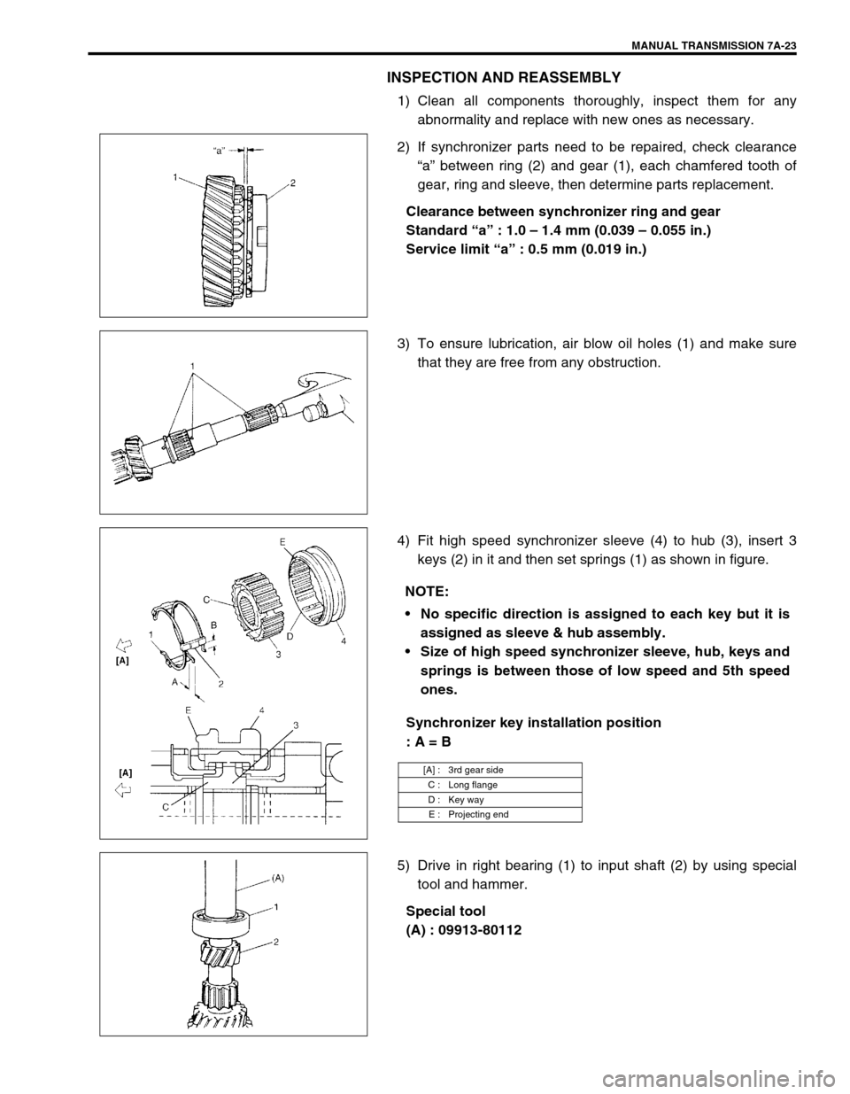
2) If synchronizer parts need to be repaired, check clearance
“a” between ring (2) and gear (1), each chamfered tooth of
gear, ring and sleeve, then determine parts replacement.
Clearance between synchronizer ring and gear
Standard “a” : 1.0 – 1.4 mm (0.039 – 0.055 in.)
Service limit “a” : 0.5 mm (0.019 in.)
3) To ensure lubrication, air blow oil holes (1) and make sure
that they are free from any obstruction.
4) Fit high speed synchronizer sleeve (4) to hub (3), insert 3
keys (2) in it and then set springs (1) as shown in figure.
Synchronizer key installation position
: A = B
5) Drive in right bearing (1) to input shaft (2) by using special
tool and hammer.
Special tool
(A) : 09913-80112
NOTE:
No specific direction is assigned to each key but it is
assigned as sleeve & hub assembly.
Size of high speed synchronizer sleeve, hub, keys and
springs is between those of low speed and 5th speed
ones.
[A] : 3rd gear side
C : Long flange
D : Key way
E : Projecting end
Page 24 of 447
7A-24 MANUAL TRANSMISSION
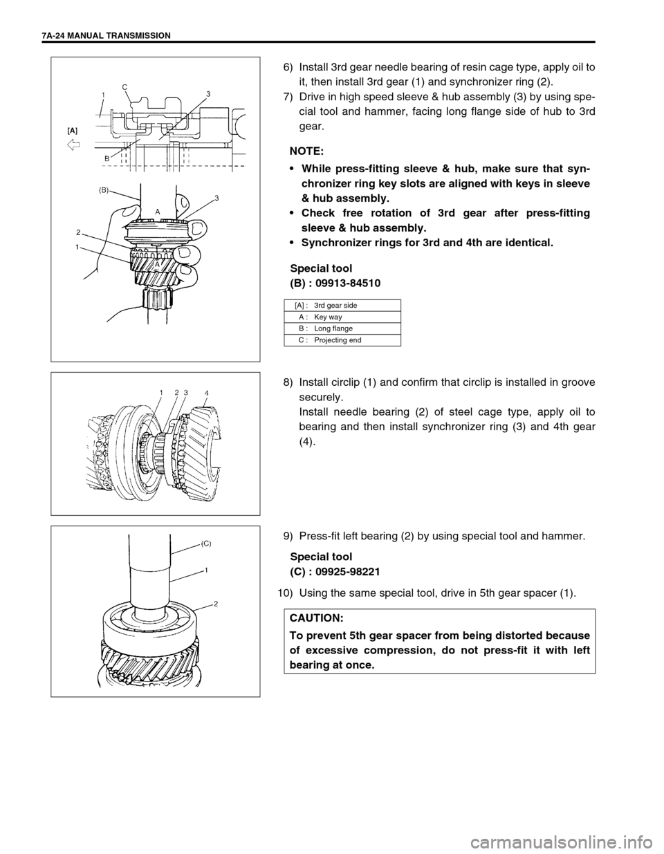
6) Install 3rd gear needle bearing of resin cage type, apply oil to
it, then install 3rd gear (1) and synchronizer ring (2).
7) Drive in high speed sleeve & hub assembly (3) by using spe-
cial tool and hammer, facing long flange side of hub to 3rd
gear.
Special tool
(B) : 09913-84510
8) Install circlip (1) and confirm that circlip is installed in groove
securely.
Install needle bearing (2) of steel cage type, apply oil to
bearing and then install synchronizer ring (3) and 4th gear
(4).
9) Press-fit left bearing (2) by using special tool and hammer.
Special tool
(C) : 09925-98221
10) Using the same special tool, drive in 5th gear spacer (1).NOTE:
While press-fitting sleeve & hub, make sure that syn-
chronizer ring key slots are aligned with keys in sleeve
& hub assembly.
Check free rotation of 3rd gear after press-fitting
sleeve & hub assembly.
Synchronizer rings for 3rd and 4th are identical.
[A] : 3rd gear side
A : Key way
B : Long flange
C : Projecting end
CAUTION:
To prevent 5th gear spacer from being distorted because
of excessive compression, do not press-fit it with left
bearing at once.
Page 26 of 447
7A-26 MANUAL TRANSMISSION
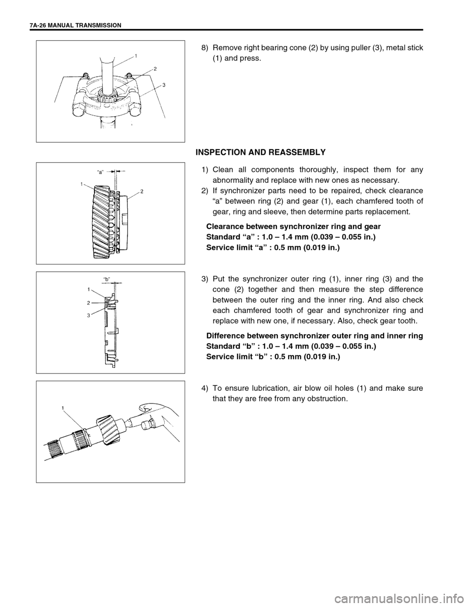
8) Remove right bearing cone (2) by using puller (3), metal stick
(1) and press.
INSPECTION AND REASSEMBLY
1) Clean all components thoroughly, inspect them for any
abnormality and replace with new ones as necessary.
2) If synchronizer parts need to be repaired, check clearance
“a” between ring (2) and gear (1), each chamfered tooth of
gear, ring and sleeve, then determine parts replacement.
Clearance between synchronizer ring and gear
Standard “a” : 1.0 – 1.4 mm (0.039 – 0.055 in.)
Service limit “a” : 0.5 mm (0.019 in.)
3) Put the synchronizer outer ring (1), inner ring (3) and the
cone (2) together and then measure the step difference
between the outer ring and the inner ring. And also check
each chamfered tooth of gear and synchronizer ring and
replace with new one, if necessary. Also, check gear tooth.
Difference between synchronizer outer ring and inner ring
Standard “b” : 1.0 – 1.4 mm (0.039 – 0.055 in.)
Service limit “b” : 0.5 mm (0.019 in.)
4) To ensure lubrication, air blow oil holes (1) and make sure
that they are free from any obstruction.
Page 27 of 447
MANUAL TRANSMISSION 7A-27
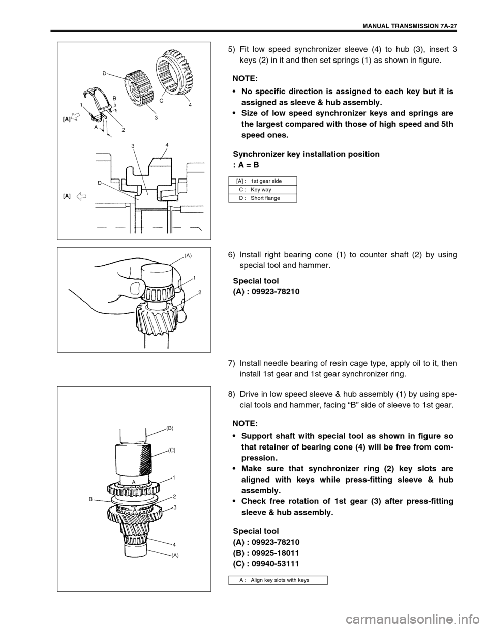
5) Fit low speed synchronizer sleeve (4) to hub (3), insert 3
keys (2) in it and then set springs (1) as shown in figure.
Synchronizer key installation position
: A = B
6) Install right bearing cone (1) to counter shaft (2) by using
special tool and hammer.
Special tool
(A) : 09923-78210
7) Install needle bearing of resin cage type, apply oil to it, then
install 1st gear and 1st gear synchronizer ring.
8) Drive in low speed sleeve & hub assembly (1) by using spe-
cial tools and hammer, facing “B” side of sleeve to 1st gear.
Special tool
(A) : 09923-78210
(B) : 09925-18011
(C) : 09940-53111 NOTE:
No specific direction is assigned to each key but it is
assigned as sleeve & hub assembly.
Size of low speed synchronizer keys and springs are
the largest compared with those of high speed and 5th
speed ones.
[A] : 1st gear side
C : Key way
D : Short flange
NOTE:
Support shaft with special tool as shown in figure so
that retainer of bearing cone (4) will be free from com-
pression.
Make sure that synchronizer ring (2) key slots are
aligned with keys while press-fitting sleeve & hub
assembly.
Check free rotation of 1st gear (3) after press-fitting
sleeve & hub assembly.
A : Align key slots with keys
Page 30 of 447
7A-30 MANUAL TRANSMISSION
2) Insert each gear shift shaft into case and check that it moves
smoothly. If it doesn’t, correct by using oilstone, reamer or
the like.
5th & Reverse Gear Shifter
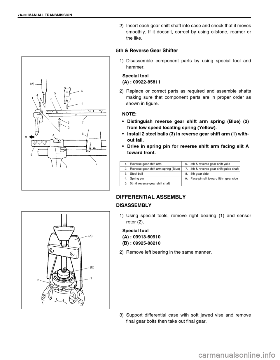
1) Disassemble component parts by using special tool and
hammer.
Special tool
(A) : 09922-85811
2) Replace or correct parts as required and assemble shafts
making sure that component parts are in proper order as
shown in figure.
DIFFERENTIAL ASSEMBLY
DISASSEMBLY
1) Using special tools, remove right bearing (1) and sensor
rotor (2).
Special tool
(A) : 09913-60910
(B) : 09925-88210
2) Remove left bearing in the same manner.
3) Support differential case with soft jawed vise and remove
final gear bolts then take out final gear. NOTE:
Distinguish reverse gear shift arm spring (Blue) (2)
from low speed locating spring (Yellow).
Install 2 steel balls (3) in reverse gear shift arm (1) with-
out fail.
Drive in spring pin for reverse shift arm facing slit A
toward front.
1. Reverse gear shift arm 6. 5th & reverse gear shift yoke
2. Reverse gear shift arm spring (Blue) 7. 5th & reverse gear shift guide shaft
3. Steel ball 8. 5th gear side
4. Spring pin A: Face pin slit toward 5thn gear side
5. 5th & reverse gear shift shaft