Page 208 of 447
7D-10 TRANSFER
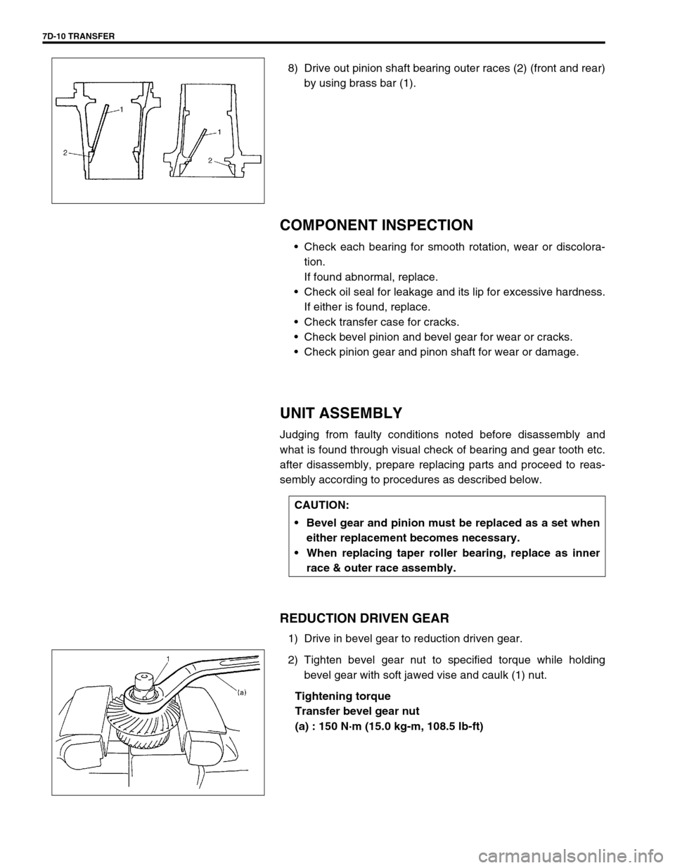
8) Drive out pinion shaft bearing outer races (2) (front and rear)
by using brass bar (1).
COMPONENT INSPECTION
Check each bearing for smooth rotation, wear or discolora-
tion.
If found abnormal, replace.
Check oil seal for leakage and its lip for excessive hardness.
If either is found, replace.
Check transfer case for cracks.
Check bevel pinion and bevel gear for wear or cracks.
Check pinion gear and pinon shaft for wear or damage.
UNIT ASSEMBLY
Judging from faulty conditions noted before disassembly and
what is found through visual check of bearing and gear tooth etc.
after disassembly, prepare replacing parts and proceed to reas-
sembly according to procedures as described below.
REDUCTION DRIVEN GEAR
1) Drive in bevel gear to reduction driven gear.
2) Tighten bevel gear nut to specified torque while holding
bevel gear with soft jawed vise and caulk (1) nut.
Tightening torque
Transfer bevel gear nut
(a) : 150 N·m (15.0 kg-m, 108.5 lb-ft)
CAUTION:
Bevel gear and pinion must be replaced as a set when
either replacement becomes necessary.
When replacing taper roller bearing, replace as inner
race & outer race assembly.
Page 211 of 447
TRANSFER 7D-13
To engage bevel pinion and gear correctly, it is prerequired to
install bevel pinion to transfer output retainer properly by using
adjusting shim (bevel pinion shim) as described on following
pages.
Shown in above page are relative positions of bevel pinion, gear
and transfer output retainer.
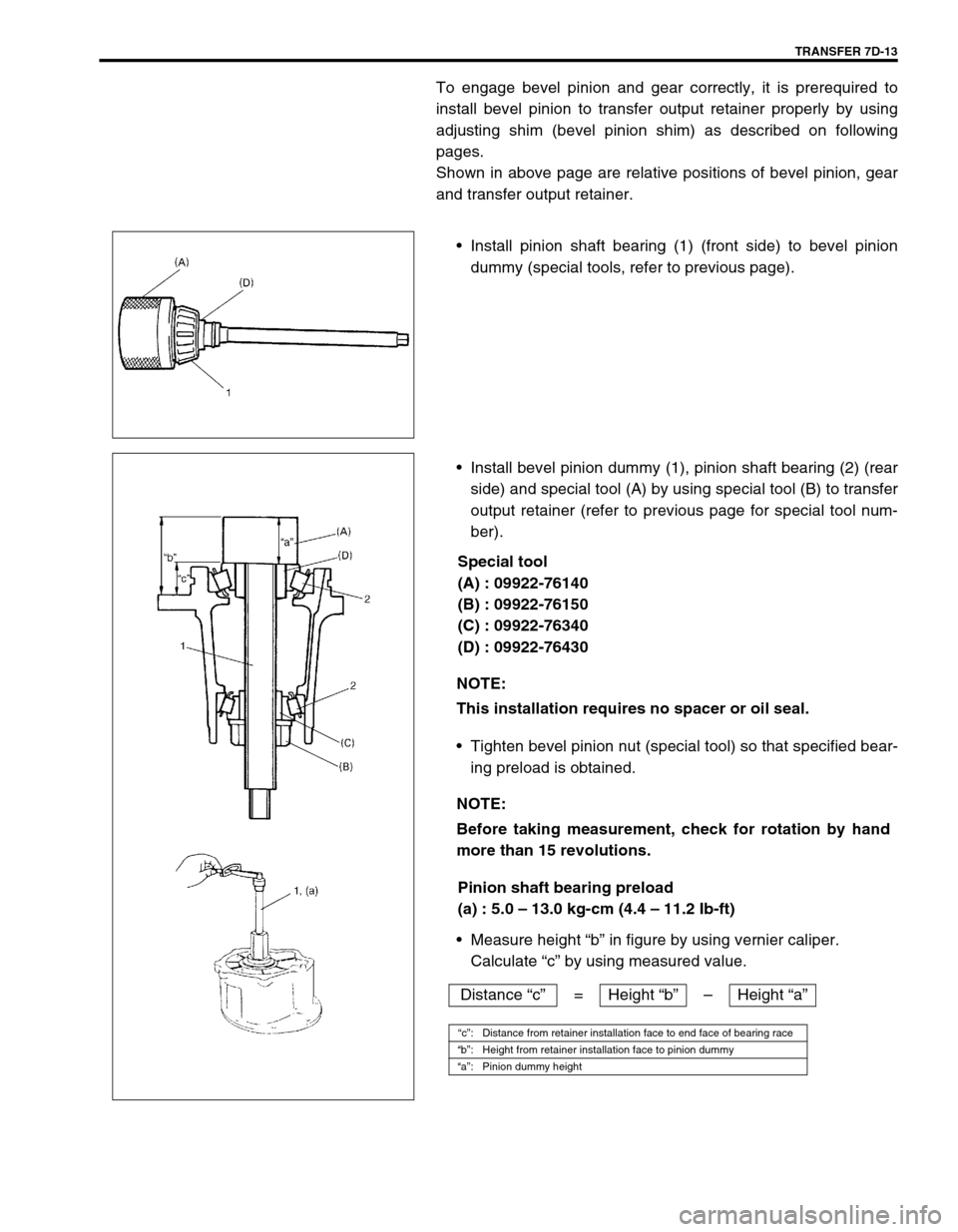
Install pinion shaft bearing (1) (front side) to bevel pinion
dummy (special tools, refer to previous page).
Install bevel pinion dummy (1), pinion shaft bearing (2) (rear
side) and special tool (A) by using special tool (B) to transfer
output retainer (refer to previous page for special tool num-
ber).
Special tool
(A) : 09922-76140
(B) : 09922-76150
(C) : 09922-76340
(D) : 09922-76430
Tighten bevel pinion nut (special tool) so that specified bear-
ing preload is obtained.
Pinion shaft bearing preload
(a) : 5.0 – 13.0 kg-cm (4.4 – 11.2 Ib-ft)
Measure height “b” in figure by using vernier caliper.
Calculate “c” by using measured value.
NOTE:
This installation requires no spacer or oil seal.
NOTE:
Before taking measurement, check for rotation by hand
more than 15 revolutions.
Distance “c”= Height “b”–Height “a”
“c”: Distance from retainer installation face to end face of bearing race
“b”: Height from retainer installation face to pinion dummy
“a”: Pinion dummy height
Page 219 of 447
TRANSFER 7D-21
Tighten mounting bolt and mounting bracket bolts and nuts
to specified torque.
Tightening torque
Transfer rear mounting bracket nuts
(a) : 50 N·m (5.0 kg-m, 36.5 lb-ft)
Transfer mounting bolt
(b) : 55 N·m (5.5 kg-m, 40.0 lb-ft)
Transfer rear mounting bracket No.2 bolts
(c) : 55 N·m (5.5 kg-m, 40.0 lb-ft)
Tighten transfer stiffener bolts (4) to specified torque.
Tightening torque
Transfer stiffener bolts (a) : 50 N·m (5.0 kg-m, 36.5 lb-ft)
Tighten exhaust pipe bolts.
Tightening torque
Exhaust pipe bolts
(a) : 50 N·m (5.0 kg-m, 36.5 lb-ft)
Install right side drive shaft, refer to Section 4A.
Install propeller shaft and tighten propeller shaft bolts and
center support bolts to specified torque (refer to Section 4B).
Fill gear oil to transfer as specified, refer to OIL CHANGE of
ON-VEHICLE SERVICE.
Check oil level and leakage.
(a)
(b)
(c)
1. Transmission
2. Transfer
3. Stiffener
1. Exhaust No.1 pipe
2. Exhaust No.2 pipe
1
(a)(a)2
Page 226 of 447
7F-4 REAR DIFFERENTIAL
ON-VEHICLE SERVICE
OIL CHANGE
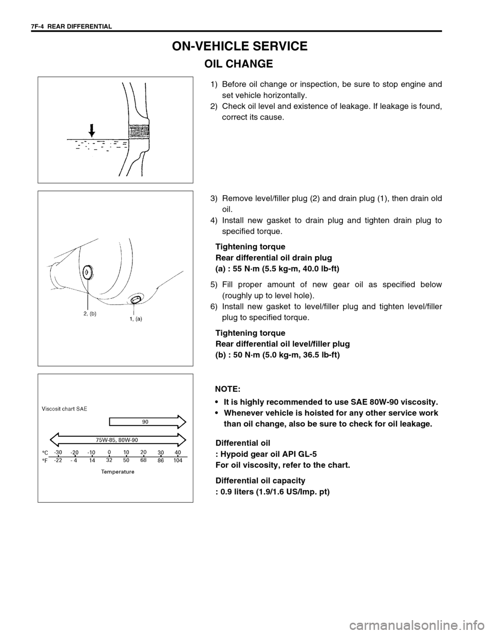
1) Before oil change or inspection, be sure to stop engine and
set vehicle horizontally.
2) Check oil level and existence of leakage. If leakage is found,
correct its cause.
3) Remove level/filler plug (2) and drain plug (1), then drain old
oil.
4) Install new gasket to drain plug and tighten drain plug to
specified torque.
Tightening torque
Rear differential oil drain plug
(a) : 55 N·m (5.5 kg-m, 40.0 lb-ft)
5) Fill proper amount of new gear oil as specified below
(roughly up to level hole).
6) Install new gasket to level/filler plug and tighten level/filler
plug to specified torque.
Tightening torque
Rear differential oil level/filler plug
(b) : 50 N·m (5.0 kg-m, 36.5 lb-ft)
Differential oil
: Hypoid gear oil API GL-5
For oil viscosity, refer to the chart.
Differential oil capacity
: 0.9 liters (1.9/1.6 US/Imp. pt)
NOTE:
It is highly recommended to use SAE 80W-90 viscosity.
Whenever vehicle is hoisted for any other service work
than oil change, also be sure to check for oil leakage.
Page 229 of 447
REAR DIFFERENTIAL 7F-7
REMOUNTING
Reverse removal procedure for installation, noting the following.
Rear Differential
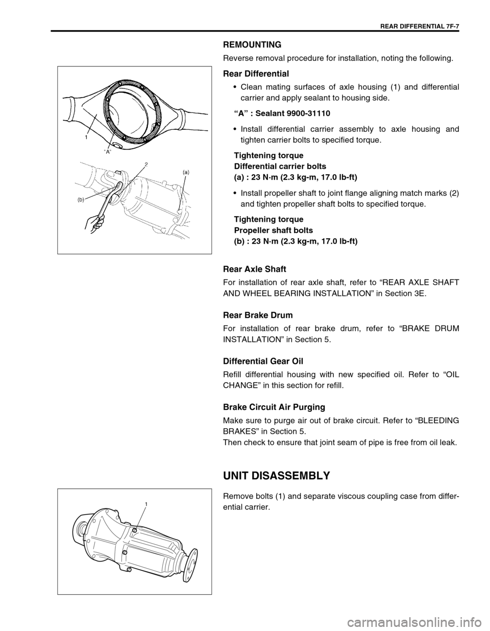
Clean mating surfaces of axle housing (1) and differential
carrier and apply sealant to housing side.
“A” : Sealant 9900-31110
Install differential carrier assembly to axle housing and
tighten carrier bolts to specified torque.
Tightening torque
Differential carrier bolts
(a) : 23 N·m (2.3 kg-m, 17.0 lb-ft)
Install propeller shaft to joint flange aligning match marks (2)
and tighten propeller shaft bolts to specified torque.
Tightening torque
Propeller shaft bolts
(b) : 23 N·m (2.3 kg-m, 17.0 lb-ft)
Rear Axle Shaft
For installation of rear axle shaft, refer to “REAR AXLE SHAFT
AND WHEEL BEARING INSTALLATION” in Section 3E.
Rear Brake Drum
For installation of rear brake drum, refer to “BRAKE DRUM
INSTALLATION” in Section 5.
Differential Gear Oil
Refill differential housing with new specified oil. Refer to “OIL
CHANGE” in this section for refill.
Brake Circuit Air Purging
Make sure to purge air out of brake circuit. Refer to “BLEEDING
BRAKES” in Section 5.
Then check to ensure that joint seam of pipe is free from oil leak.
UNIT DISASSEMBLY
Remove bolts (1) and separate viscous coupling case from differ-
ential carrier.1
Page 231 of 447
REAR DIFFERENTIAL 7F-9
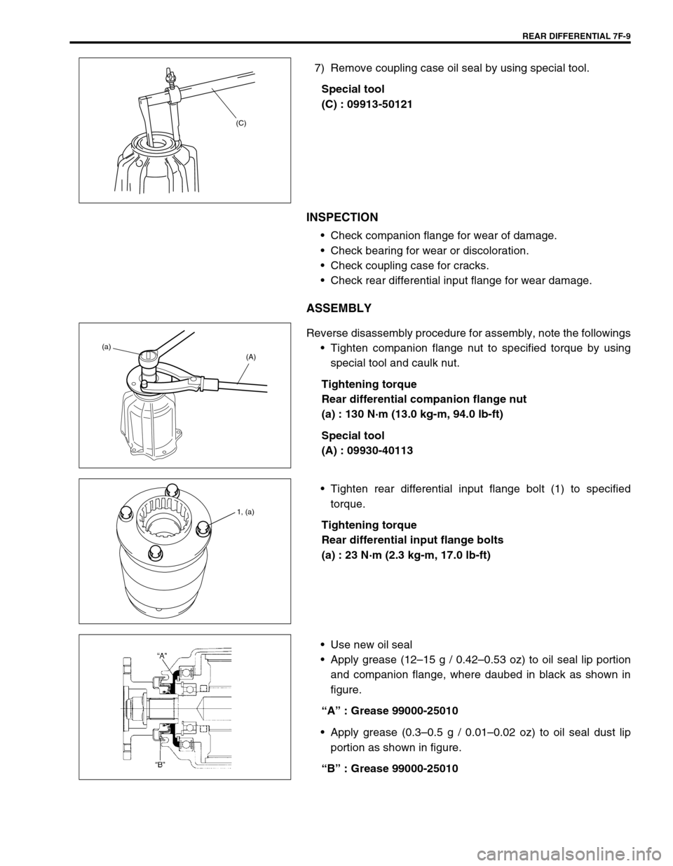
7) Remove coupling case oil seal by using special tool.
Special tool
(C) : 09913-50121
INSPECTION
Check companion flange for wear of damage.
Check bearing for wear or discoloration.
Check coupling case for cracks.
Check rear differential input flange for wear damage.
ASSEMBLY
Reverse disassembly procedure for assembly, note the followings
Tighten companion flange nut to specified torque by using
special tool and caulk nut.
Tightening torque
Rear differential companion flange nut
(a) : 130 N·m (13.0 kg-m, 94.0 lb-ft)
Special tool
(A) : 09930-40113
Tighten rear differential input flange bolt (1) to specified
torque.
Tightening torque
Rear differential input flange bolts
(a) : 23 N·m (2.3 kg-m, 17.0 lb-ft)
Use new oil seal
Apply grease (12–15 g / 0.42–0.53 oz) to oil seal lip portion
and companion flange, where daubed in black as shown in
figure.
“A” : Grease 99000-25010
Apply grease (0.3–0.5 g / 0.01–0.02 oz) to oil seal dust lip
portion as shown in figure.
“B” : Grease 99000-25010
(C)
(a)
(A)
1, (a)
Page 237 of 447
REAR DIFFERENTIAL 7F-15
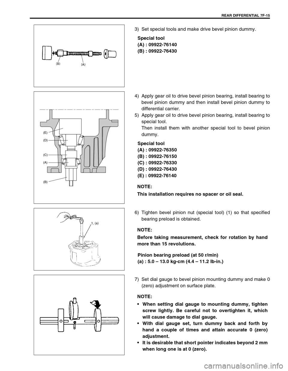
3) Set special tools and make drive bevel pinion dummy.
Special tool
(A) : 09922-76140
(B) : 09922-76430
4) Apply gear oil to drive bevel pinion bearing, install bearing to
bevel pinion dummy and then install bevel pinion dummy to
differential carrier.
5) Apply gear oil to drive bevel pinion bearing, install bearing to
special tool.
Then install them with another special tool to bevel pinion
dummy.
Special tool
(A) : 09922-76350
(B) : 09922-76150
(C) : 09922-76330
(D) : 09922-76430
(E) : 09922-76140
6) Tighten bevel pinion nut (special tool) (1) so that specified
bearing preload is obtained.
Pinion bearing preload (at 50 r/min)
(a) : 5.0 – 13.0 kg-cm (4.4 – 11.2 lb-in.)
7) Set dial gauge to bevel pinion mounting dummy and make 0
(zero) adjustment on surface plate.
NOTE:
This installation requires no spacer or oil seal.
(E)
(D)
(C)
(A)
(B)
NOTE:
Before taking measurement, check for rotation by hand
more than 15 revolutions.
NOTE:
When setting dial gauge to mounting dummy, tighten
screw lightly. Be careful not to overtighten it, which
will cause damage to dial gauge.
With dial gauge set, turn dummy back and forth by
hand a couple of times and attain accurate 0 (zero)
adjustment.
It is desirable that short pointer indicates beyond 2 mm
when long one is at 0 (zero).
Page 239 of 447
REAR DIFFERENTIAL 7F-17
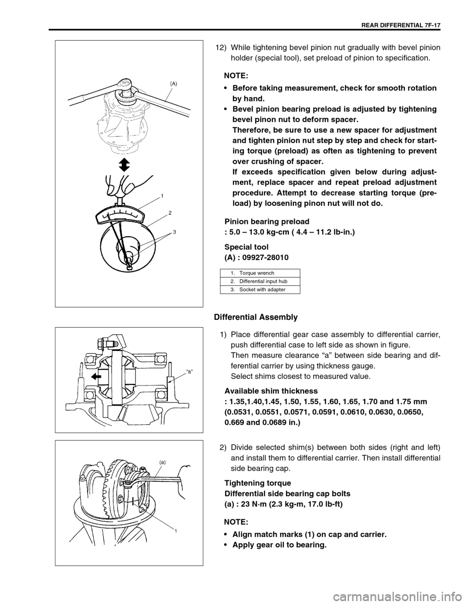
12) While tightening bevel pinion nut gradually with bevel pinion
holder (special tool), set preload of pinion to specification.
Pinion bearing preload
: 5.0 – 13.0 kg-cm ( 4.4 – 11.2 lb-in.)
Special tool
(A) : 09927-28010
Differential Assembly
1) Place differential gear case assembly to differential carrier,
push differential case to left side as shown in figure.
Then measure clearance “a” between side bearing and dif-
ferential carrier by using thickness gauge.
Select shims closest to measured value.
Available shim thickness
: 1.35,1.40,1.45, 1.50, 1.55, 1.60, 1.65, 1.70 and 1.75 mm
(0.0531, 0.0551, 0.0571, 0.0591, 0.0610, 0.0630, 0.0650,
0.669 and 0.0689 in.)
2) Divide selected shim(s) between both sides (right and left)
and install them to differential carrier. Then install differential
side bearing cap.
Tightening torque
Differential side bearing cap bolts
(a) : 23 N·m (2.3 kg-m, 17.0 lb-ft) NOTE:
Before taking measurement, check for smooth rotation
by hand.
Bevel pinion bearing preload is adjusted by tightening
bevel pinon nut to deform spacer.
Therefore, be sure to use a new spacer for adjustment
and tighten pinion nut step by step and check for start-
ing torque (preload) as often as tightening to prevent
over crushing of spacer.
If exceeds specification given below during adjust-
ment, replace spacer and repeat preload adjustment
procedure. Attempt to decrease starting torque (pre-
load) by loosening pinon nut will not do.
1. Torque wrench
2. Differential input hub
3. Socket with adapter
NOTE:
Align match marks (1) on cap and carrier.
Apply gear oil to bearing.