2000 SUZUKI SWIFT relay
[x] Cancel search: relayPage 48 of 447

7B-6 AUTOMATIC TRANSMISSION (4 A/T)
ELECTRONIC SHIFT CONTROL SYSTEM
1. Engine 15. O/D off switch F. Range signal
2. Transmission 16. Combination meter (O/D off lamp) G. O/D off switch signal
3. TCM 17. A/C compressor G’. O/D off lamp signal
4. ECM 18. Brake lamp switch H. A/C clutch signal
5. Input shaft speed sensor (Turbine rev. sensor) 19. Monitor connector NO. 2 I. Brake signal
6. Transmission temp. sensor (A/T fluid temp. sensor) 20. Suzuki scan tool J. Diagnosis switch signal
7. TCC solenoid (Lock-up solenoid) 21. Ignition switch K. Serial communication with Suzuki scan tool
8. Shift solenoid-A (Shift solenoid No.1) 22. Battery L. Power supply
9. Shift solenoid-B (Shift solenoid No.2) 23. A/T relay M. Throttle opening signal
10. Shift solenoid-C (Shift solenoid No.3) A. Turbine speed signal N. Engine coolant temp./Barometric pressure signal
11. Shift solenoid-D (Shift solenoid No.4) B. A/T fluid temp signal O. Idle up signal
12. Shift solenoid-E (Shift solenoid No.5) C. TCC (lock-up) control signal P. A/T failure signal
13. Output shaft speed sensor (A/T VSS) D. Shift control signal Q. Engine speed (rev.) signal.
14. Transmission range sensor (Shift switch) E. A/T output shaft speed signal
14
3
19
15
1816
14 13 5
2
7
9
12
8
6
10 17
11
Page 49 of 447

AUTOMATIC TRANSMISSION (4 A/T) 7B-7
TRANSMISSION CONTROL MODULE (TCM)
TCM is an electronic circuit component that controls gear shift, idle-up according to the signal from each sensor.
Also it has learning control function for performing optimum control. It is a microcomputer consisting of an IC,
transistor, diode, etc. It is installed behind glove box.
1.“O/D OFF” lamp (in combination meter) 11. Backup lamp 21. Dropping resistor
2.“O/D” off switch 12. Shift indicator (if equipped) 22. Output shaft speed sensor (A/T VSS)
3. Monitor connector No.2 13. A/T 23. Input shaft speed sensor (Turbine rev. sensor)
4. Brake lamp 14. Transmission temperature sensor
(A/T fluid temp. sensor)24. A/T power source relay
5. Brake lamp switch 15. Shift solenoid-A (Shift solenoid No.1) 25. Ignition switch
6. ECM 16. Shift solenoid-B (Shift solenoid No.2) 26. DLC
7. A/C clutch 17. Shift solenoid-C (Shift solenoid No.3) 27. Barometric pressure sensor
8. Transmission range sensor (Shift switch) 18. Shift solenoid-D (Shift solenoid No.4) 28. Solenoid power relay
9. Shift lock solenoid switch (if equipped) 19. Shift solenoid-E (Shift solenoid No.5) 29. Terminal arrangement of TCM coupler
(Viewed from harness side)
10. Shift lock solenoid (if equipped) 20. TCC solenoid (Lock-up solenoid)
C41-14
C41-21
C42-5
C41-23
G02-16
BLKBLKLT GRN/ RED/BLU BLU/ORN
PPL/YEL
3
45
+BB
GRN/WHT
LT BLU
PPL
WHT/BLK
BLK/WHT
BRN
PNK/BLK 6
7
8
C44-8
C43-8
C44-18
C44-20
C43-5
C44-5
910
ORN
RED
GRN/ORN RED/BLK
GRNC43-1
C43-2
C43-3
C43-9
C43-10
C43-11 GRN/YEL
BLU/WHT P
R
N
D
2
L11
12C44-21
C44-17
C43-4
C44-4
12V 12V
12V
12V
12V IG1
IG115V
5VC44-3
C44-16
C44-10
C44-23
C44-24
C44-25
C44-26
C44-22
C44-11
C44-12
C44-13
C43-6
C43-14
C43-13
C43-7
C43-15
C44-2
C44-15
C43-12
BLU BLUBLK
BLK BLK
BLU/YEL
YEL/BLK RED/WHT WHT BLU/ORN RED/BLU GRY/BLU
BLK/YEL WHT/BLU
BRN/WHT BRN/WHT BRN WHT/RED
BLK/YEL
BRN/YEL BLU/RED
GRY/RED13
14
15
16
17
19
20 BRN
21
22
23
+BB 24
25
26
12V
12V
12V
12V
18
12V
IG1
IG11
5V
1
2
28
27
Page 50 of 447

7B-8 AUTOMATIC TRANSMISSION (4 A/T)
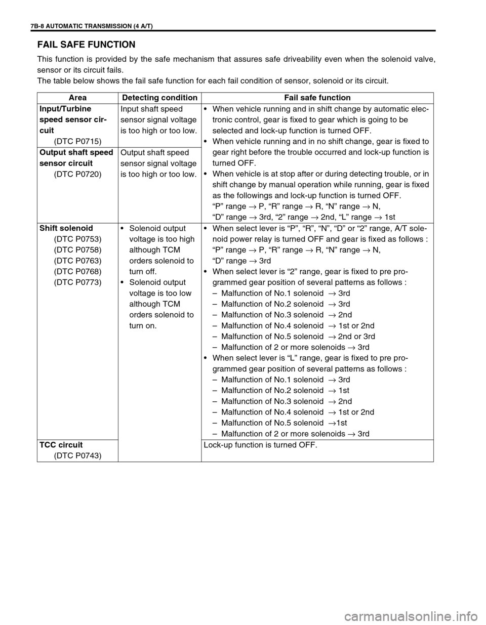
FAIL SAFE FUNCTION
This function is provided by the safe mechanism that assures safe driveability even when the solenoid valve,
sensor or its circuit fails.
The table below shows the fail safe function for each fail condition of sensor, solenoid or its circuit.
Area Detecting condition Fail safe function
Input/Turbine
speed sensor cir-
cuit
(DTC P0715)Input shaft speed
sensor signal voltage
is too high or too low.When vehicle running and in shift change by automatic elec-
tronic control, gear is fixed to gear which is going to be
selected and lock-up function is turned OFF.
When vehicle running and in no shift change, gear is fixed to
gear right before the trouble occurred and lock-up function is
turned OFF.
When vehicle is at stop after or during detecting trouble, or in
shift change by manual operation while running, gear is fixed
as the followings and lock-up function is turned OFF.
“P” range →
P, “R” range →
R, “N” range →
N,
“D” range →
3rd, “2” range →
2nd, “L” range →
1st Output shaft speed
sensor circuit
(DTC P0720)Output shaft speed
sensor signal voltage
is too high or too low.
Shift solenoid
(DTC P0753)
(DTC P0758)
(DTC P0763)
(DTC P0768)
(DTC P0773)Solenoid output
voltage is too high
although TCM
orders solenoid to
turn off.
Solenoid output
voltage is too low
although TCM
orders solenoid to
turn on.When select lever is “P”, “R”, “N”, “D” or “2” range, A/T sole-
noid power relay is turned OFF and gear is fixed as follows :
“P” range →
P, “R” range →
R, “N” range →
N,
“D” range →
3rd
When select lever is “2” range, gear is fixed to pre pro-
grammed gear position of several patterns as follows :
–Malfunction of No.1 solenoid →
3rd
–Malfunction of No.2 solenoid →
3rd
–Malfunction of No.3 solenoid →
2nd
–Malfunction of No.4 solenoid →
1st or 2nd
–Malfunction of No.5 solenoid →
2nd or 3rd
–Malfunction of 2 or more solenoids →
3rd
When select lever is “L” range, gear is fixed to pre pro-
grammed gear position of several patterns as follows :
–Malfunction of No.1 solenoid →
3rd
–Malfunction of No.2 solenoid →
1st
–Malfunction of No.3 solenoid →
2nd
–Malfunction of No.4 solenoid →
1st or 2nd
–Malfunction of No.5 solenoid →
1st
–Malfunction of 2 or more solenoids →
3rd
TCC circuit
(DTC P0743)Lock-up function is turned OFF.
Page 52 of 447

7B-10 AUTOMATIC TRANSMISSION (4 A/T)
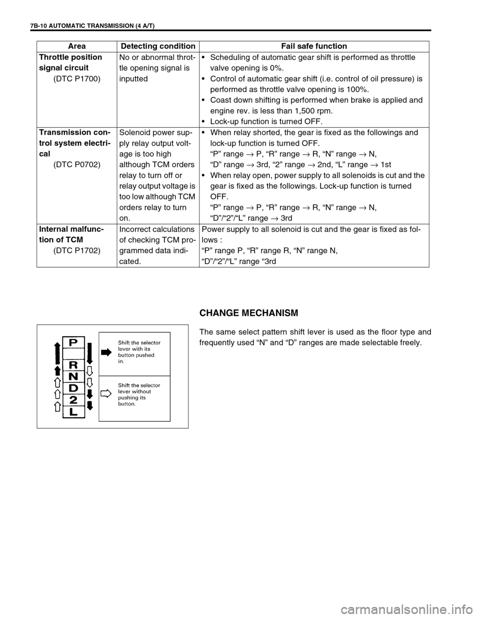
CHANGE MECHANISM
The same select pattern shift lever is used as the floor type and
frequently used “N” and “D” ranges are made selectable freely. Throttle position
signal circuit
(DTC P1700)No or abnormal throt-
tle opening signal is
inputtedScheduling of automatic gear shift is performed as throttle
valve opening is 0%.
Control of automatic gear shift (i.e. control of oil pressure) is
performed as throttle valve opening is 100%.
Coast down shifting is performed when brake is applied and
engine rev. is less than 1,500 rpm.
Lock-up function is turned OFF.
Transmission con-
trol system electri-
cal
(DTC P0702)Solenoid power sup-
ply relay output volt-
age is too high
although TCM orders
relay to turn off or
relay output voltage is
too low although TCM
orders relay to turn
on.When relay shorted, the gear is fixed as the followings and
lock-up function is turned OFF.
“P” range →
P, “R” range →
R, “N” range →
N,
“D” range →
3rd, “2” range →
2nd, “L” range →
1st
When relay open, power supply to all solenoids is cut and the
gear is fixed as the followings. Lock-up function is turned
OFF.
“P” range →
P, “R” range →
R, “N” range →
N,
“D”/“2”/“L” range →
3rd
Internal malfunc-
tion of TCM
(DTC P1702)Incorrect calculations
of checking TCM pro-
grammed data indi-
cated.Power supply to all solenoid is cut and the gear is fixed as fol-
lows :
“P” range P, “R” range R, “N” range N,
“D”/“2”/“L” range “3rd Area Detecting condition Fail safe function
Page 72 of 447

7B-30 AUTOMATIC TRANSMISSION (4 A/T)
TCM POWER AND GROUND CIRCUIT CHECK
1. Battery 4. Circuit fuse (IG) 7. TCM
2. Main fuse 5. Ground
3. Ignition switch 6. A/T relay
DTC DETECTING CONDITION
Automatic transmission doesn’t shift to 1st gear at vehicle start in “D” range.
Step Action Yes No
1 Check voltage between terminal “C44-2” of
TCM coupler and body ground with ignition
switch ON.
Is it 10 – 14 V?Go to Step 2. YEL/BLK wire open or
faulty
A/T relay.
2 Check voltage between terminal “C44-15” of
TCM coupler and body ground with ignition
switch ON.
Is it about 0 V?Poor “C44-2” or “C44-15”
connection.
If all above are OK,
replace known-good TCM
and recheck.“BLK” wire open.
Page 94 of 447

7B-52 AUTOMATIC TRANSMISSION (4 A/T)
DTC P0702/P1702 (DTC No.52)TRANSMISSION CONTROL SYSTEM ELECTRICAL OR
INTERNAL MALFUNCTION OF TCM
1. TCM 3. A/T relay
2. Ignition switch 4. TCM coupler (viewed from harness side)
DTC DETECTING CONDITION
Relay output voltage too high although TCM orders the relay to turn OFF or relay output voltage too low
although TCM orders the relay to turn on.
Incorrect calculations of checking TCM programmed data indicated.
Step Action Yes No
1 1) Turn ignition switch ON.
2) Erase all DTCs referring to “HOW TO
CLEAR DTC” in this section.
3) Turn ignition switch OFF.
4) Turn ignition switch ON once again and
check for any DTC.
Is it DTC P1702 (DTC No.52) or P0702 (DTC
No.52)?Replace TCM. Could be a temporary
malfunction of the TCM.
Page 245 of 447

BODY ELECTRICAL SYSTEM 8-1
6F1
6F2
6G
6H
6K
7A
7A1
7B1
7C1
7D
7E
7F
8A
8
8D
8E
9
10
10A
10B
SECTION 8
BODY ELECTRICAL SYSTEM
CONTENTS
DIAGNOSIS ........................................................ 8-3
HEADLIGHT .................................................... 8-3
HEADLIGHTS WITH LEVELING SYSTEM
(IF EQUIPPED) ............................................... 8-3
TURN SIGNAL AND HAZARD WARNING
LIGHT .............................................................. 8-3
CLEARANCE, TAIL AND LICENSE
PLATE LIGHT ................................................. 8-4
BACK-UP LIGHT ............................................. 8-4
BRAKE LIGHT ................................................ 8-4
FRONT FOG LIGHT (IF EQUIPPED) ............. 8-4
REAR FOG LIGHT (IF EQUIPPED) ................ 8-4
SPEEDOMETER AND VSS ............................ 8-5
FUEL METER AND FUEL LEVEL SENSOR
(GAUGE UNIT) ............................................... 8-5
ENGINE COOLANT TEMPERATURE (ECT)
METER AND ECT SENSOR ........................... 8-5
OIL PRESSURE WARNING LIGHT ................ 8-5
BRAKE AND PARKING BRAKE WARNING
LIGHT .............................................................. 8-6
REAR WINDOW DEFOGGER ........................ 8-6
WIPERS AND WASHERS .............................. 8-6
FRONT WIPER AND WASHER .................. 8-6
REAR WIPER AND WASHER (IF
EQUIPPED)................................................. 8-6
POWER WINDOW CONTROL SYSTEM
(IF EQUIPPED) ............................................... 8-7
CIGARETTE LIGHTER ................................... 8-7
POWER DOOR LOCK CONTROL SYSTEM
(IF EQUIPPED) ............................................... 8-7
KEYLESS ENTRY SYSTEM (IF
EQUIPPED) .................................................... 8-7POWER DOOR MIRROR CONTROL
SYSTEM (IF EQUIPPED) ............................... 8-8
INTERIOR LIGHT ........................................... 8-8
HORN ............................................................. 8-8
IGNITION KEY REMAINDER (IF EQUIPPED)
AND LIGHT REMAINDER WARNING
BUZZER.......................................................... 8-8
SEAT BELT WARNING LIGHT (IF
EQUIPPED) .................................................... 8-8
FRONT SEAT HEATER (IF EQUIPPED) ....... 8-9
ON-VEHICLE SERVICE ..................................... 8-9
CAUTIONS IN SERVICING ............................ 8-9
HEADLIGHT ................................................... 8-9
HEADLIGHT SWITCH ................................ 8-9
HEADLIGHT ASSEMBLY ......................... 8-10
HEADLIGHT BULB ................................... 8-10
HEADLIGHT AIMING ADJUSTMENT
WITH SCREEN ......................................... 8-11
HEADLIGHT LEVELING SWITCH (IF
EQUIPPED) .............................................. 8-12
TURN SIGNAL AND HAZARD WARNING
LIGHTS ......................................................... 8-12
TURN SIGNAL LIGHT SWITCH ............... 8-12
REMOVAL AND INSTALLATION ............. 8-12
TURN SIGNAL AND HAZARD RELAY ..... 8-13
HAZARD SWITCH .................................... 8-13
FRONT FOG LIGHTS (IF EQUIPPED)......... 8-13
FRONT FOG LIGHT SWITCH .................. 8-13
REAR FOG LIGHT (IF EQUIPPED) ............. 8-14
REAR FOG LIGHT SWITCH..................... 8-14
IGNITION SWITCH ....................................... 8-14
COMBINATION METER ............................... 8-15 WARNING:
For vehicles equipped with Supplemental Restraint (Air Bag) System :
Service on and around the air bag system components or wiring must be performed only by an
authorized SUZUKI dealer. Refer to “Air Bag System Components and Wiring Location View” under
“General Description” in air bag system section in order to confirm whether you are performing ser-
vice on or near the air bag system components or wiring. Please observe all WARNINGS and “Ser-
vice Precautions” under “On-Vehicle Service” in air bag system section before performing service
on or around the air bag system components or wiring. Failure to follow WARNINGS could result in
unintentional activation of the system or could render the system inoperative. Either of these two
conditions may result in severe injury.
Technical service work must be started at least 90 seconds after the ignition switch is turned to the
“LOCK” position and the negative cable is disconnected from the battery. Otherwise, the system
may be activated by reserve energy in the Sensing and Diagnostic Module (SDM).
Page 247 of 447

BODY ELECTRICAL SYSTEM 8-3
DIAGNOSIS
HEADLIGHT
HEADLIGHTS WITH LEVELING SYSTEM (IF EQUIPPED)
TURN SIGNAL AND HAZARD WARNING LIGHT
NOTE:
Fuse name (“ ”) in the table below is shown on the fuse box cover.
Condition Possible Cause Correction
Headlights do not light
upLighting or dimmer switch faulty Check headlight switch.
Headlight R and L fuses blown Replace fuse to check for short.
Wiring or grounding faulty Repair circuit.
Only one headlight
does not light upBulb blown Replace bulb.
Headlight R or L fuse blown Replace fuse to check for short.
Wiring or grounding faulty Repair circuit.
Only one beam (“Hi”
or “Lo”) does not lightBulb blown Replace bulb.
Lighting or dimmer switch faulty Check switch.
Wiring or grounding faulty Repair circuit.
Condition Possible Cause Correction
Both headlights do
not move“WIPER/WASHER” fuse blown Replace fuse to check for short.
Leveling switch faulty Check switch.
Supply voltage too low Recharge or replace battery.
One of headlights
(either Right or Left)
does not moveSocket, wiring or grounding faulty Repair.
Actuator faulty Check actuator.
Vehicle body around headlight deformed Repair body.
Headlight assembly itself deformed Replace headlight assembly.
Condition Possible Cause Correction
Flash rate high or one
side only flashesBulb blown on “flash rate high”-side Replace bulb.
Incorrect bulb Replace bulb.
Turn signal/hazard warning relay faulty Check relay.
Open circuit or high resistance existing
between combination switch (turn signal/hazard
warning switch) and light on one sideRepair circuit.
Wiring or grounding faulty Repair circuit.
No flashing
“HORN HAZARD” fuse and/or “TURN/BACK”
fuse(s) blownReplace fuse(s) to check for short.
Open circuit or high resistance existing
between battery and switchRepair circuit.
Turn signal/hazard relay faulty Check relay.
Combination switch or hazard switch faulty Check switch.
Wiring or grounding faulty Repair circuit.
Flash rate low
Supply voltage low Check charging system.
Turn signal/hazard relay faulty Check relay.