Page 233 of 447

REAR DIFFERENTIAL 7F-11
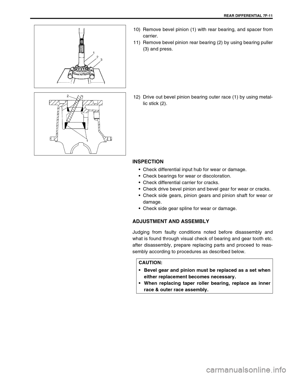
10) Remove bevel pinion (1) with rear bearing, and spacer from
carrier.
11) Remove bevel pinion rear bearing (2) by using bearing puller
(3) and press.
12) Drive out bevel pinion bearing outer race (1) by using metal-
lic stick (2).
INSPECTION
Check differential input hub for wear or damage.
Check bearings for wear or discoloration.
Check differential carrier for cracks.
Check drive bevel pinion and bevel gear for wear or cracks.
Check side gears, pinion gears and pinion shaft for wear or
damage.
Check side gear spline for wear or damage.
ADJUSTMENT AND ASSEMBLY
Judging from faulty conditions noted before disassembly and
what is found through visual check of bearing and gear tooth etc.
after disassembly, prepare replacing parts and proceed to reas-
sembly according to procedures as described below.
CAUTION:
Bevel gear and pinion must be replaced as a set when
either replacement becomes necessary.
When replacing taper roller bearing, replace as inner
race & outer race assembly.
Page 242 of 447

7F-20 REAR DIFFERENTIAL
UNIT ASSEMBLY
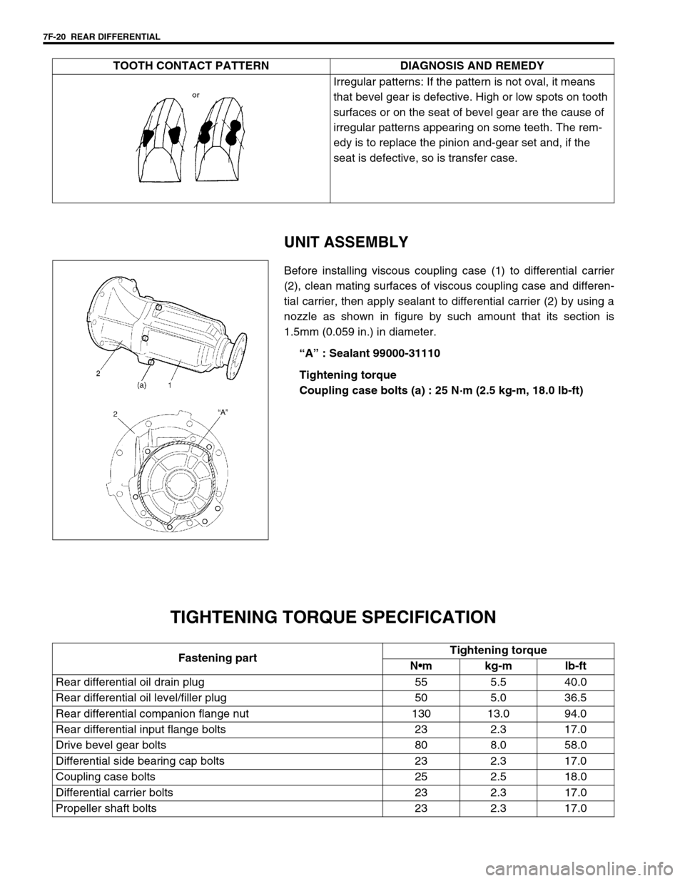
Before installing viscous coupling case (1) to differential carrier
(2), clean mating surfaces of viscous coupling case and differen-
tial carrier, then apply sealant to differential carrier (2) by using a
nozzle as shown in figure by such amount that its section is
1.5mm (0.059 in.) in diameter.
“A” : Sealant 99000-31110
Tightening torque
Coupling case bolts (a) : 25 N·m (2.5 kg-m, 18.0 lb-ft)
TIGHTENING TORQUE SPECIFICATION
Irregular patterns: If the pattern is not oval, it means
that bevel gear is defective. High or low spots on tooth
surfaces or on the seat of bevel gear are the cause of
irregular patterns appearing on some teeth. The rem-
edy is to replace the pinion and-gear set and, if the
seat is defective, so is transfer case. TOOTH CONTACT PATTERN DIAGNOSIS AND REMEDY
Fastening partTightening torque
Nm kg-m lb-ft
Rear differential oil drain plug 55 5.5 40.0
Rear differential oil level/filler plug 50 5.0 36.5
Rear differential companion flange nut 130 13.0 94.0
Rear differential input flange bolts 23 2.3 17.0
Drive bevel gear bolts 80 8.0 58.0
Differential side bearing cap bolts 23 2.3 17.0
Coupling case bolts 25 2.5 18.0
Differential carrier bolts 23 2.3 17.0
Propeller shaft bolts 23 2.3 17.0
Page 243 of 447
REAR DIFFERENTIAL 7F-21
REQUIRED SERVICE MATERIAL
SPECIAL TOOL
MaterialRecommended SUZUKI product
(Part Number)Use
Thread lock cement THREAD LOCK CEMENT 1322
(99000-32110)Bevel gear bolts
Lithium grease SUZUKI SUPER GREASE A
(99000-25010)Oil seal lips
Sealant SUZUKI BOND NO. 1215
(99000-31110)Thread part of differential carrier bolt
Mating surface of differential housing
Mating surface of rear axle housing
Mating surface of viscous coupling case
09951-16060 09951-76010 09927-28010 09925-88210
Lower arm bush remover Bearing installer Bevel pinion holder Bearing puller attachment
09913-60910 09913-80112 09900-20701 09900-20606
Bearing puller Bearing installer Magnetic stand Dial gauge
09922-76140 09922-76150 09922-76330 09922-76430
Bevel pinion shaft Bevel pinion nut Rear collar Front collar
Page 244 of 447
7F-22 REAR DIFFERENTIAL
09922-76350 09922-76120 09922-76250 09924-74510
Gauge block Dummy shaft Bevel gear dummy Bearing installer handle
09925-68210 09925-98210 09924-84510-002 09930-40113
Bearing installer Bearing installer Bearing installer Flange holder
09913-65135 09913-50121
Bearing puller Oil seal remover
Page 347 of 447

BODY SERVICE 9-43
INSTALLATION
Reverse removal procedure to install front door lock assembly
noting the following instructions.
Apply grease to sliding parts of door latch assembly.
Grease 99000-25010
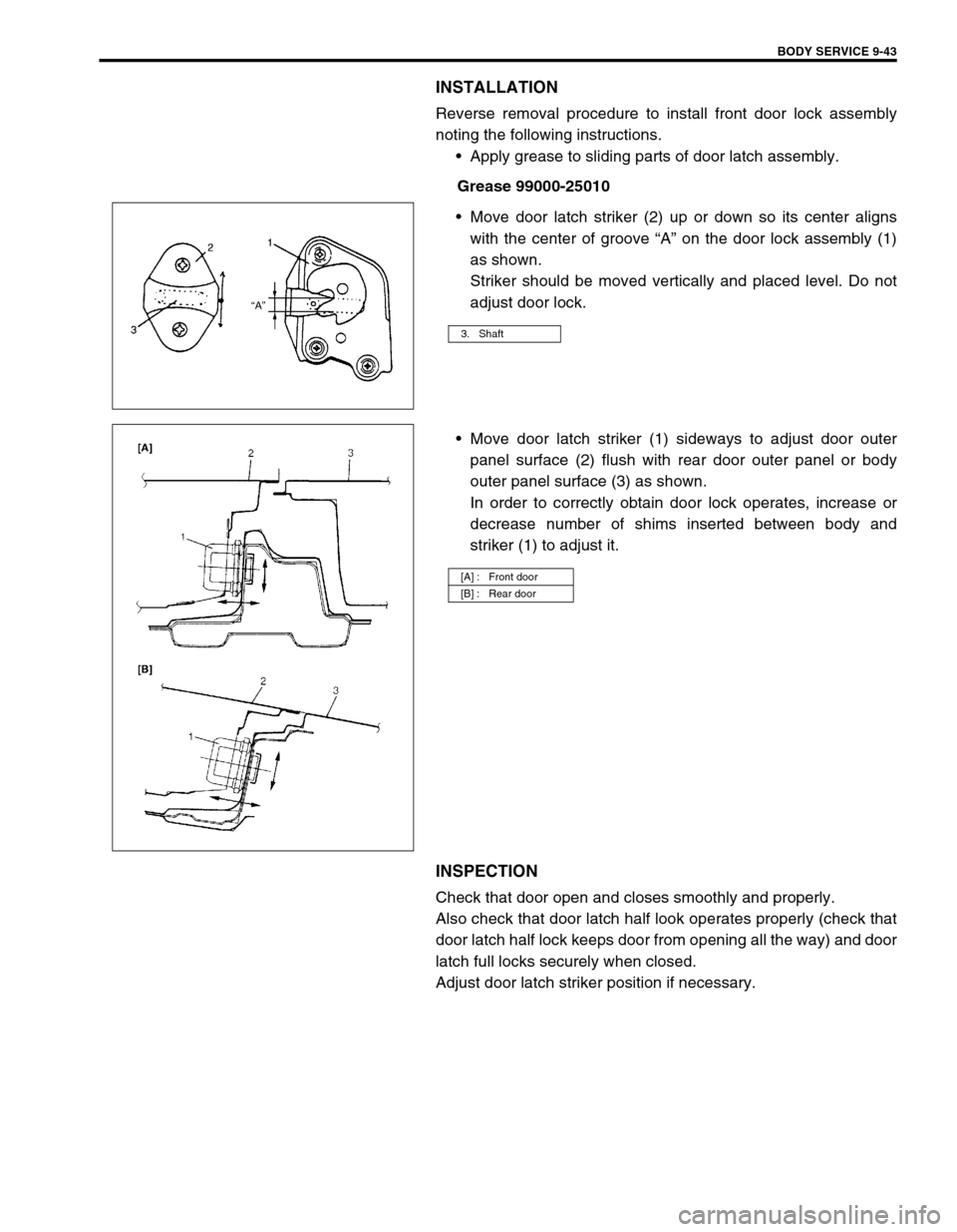
Move door latch striker (2) up or down so its center aligns
with the center of groove “A” on the door lock assembly (1)
as shown.
Striker should be moved vertically and placed level. Do not
adjust door lock.
Move door latch striker (1) sideways to adjust door outer
panel surface (2) flush with rear door outer panel or body
outer panel surface (3) as shown.
In order to correctly obtain door lock operates, increase or
decrease number of shims inserted between body and
striker (1) to adjust it.
INSPECTION
Check that door open and closes smoothly and properly.
Also check that door latch half look operates properly (check that
door latch half lock keeps door from opening all the way) and door
latch full locks securely when closed.
Adjust door latch striker position if necessary.
3. Shaft
[A] : Front door
[B] : Rear door
Page 427 of 447

AIR BAG SYSTEM 10B-53
REPAIRS AND INSPECTIONS REQUIRED AFTER AN ACCIDENT
ACCIDENT WITH DEPLOYMENT/ACTIVA-
TION - COMPONENT REPLACEMENT
The following components must be replaced.
Driver and passenger air bag (inflator) modules
Driver and passenger seat belt pretensioners
SDM
–Replace with new one as an assembly.
ACCIDENT WITH OR WITHOUT DEPLOY-
MENT/ACTIVATION - COMPONENT INSPEC-
TIONS
Certain air bag system components must be inspected after any
crash, whether the air bag system activated or not.
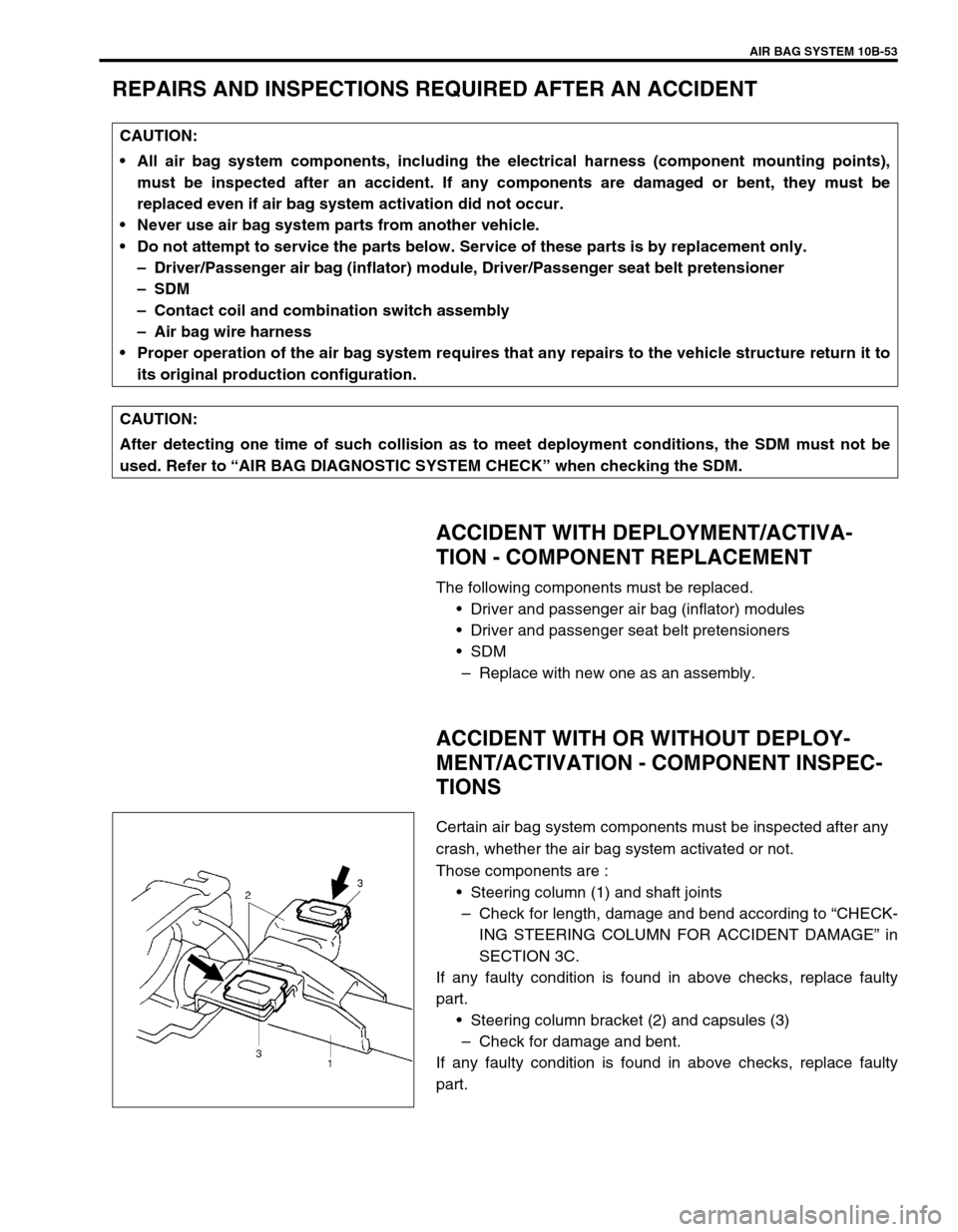
Those components are :
Steering column (1) and shaft joints
–Check for length, damage and bend according to “CHECK-
ING STEERING COLUMN FOR ACCIDENT DAMAGE” in
SECTION 3C.
If any faulty condition is found in above checks, replace faulty
part.
Steering column bracket (2) and capsules (3)
–Check for damage and bent.
If any faulty condition is found in above checks, replace faulty
part. CAUTION:
All air bag system components, including the electrical harness (component mounting points),
must be inspected after an accident. If any components are damaged or bent, they must be
replaced even if air bag system activation did not occur.
Never use air bag system parts from another vehicle.
Do not attempt to service the parts below. Service of these parts is by replacement only.
–Driver/Passenger air bag (inflator) module, Driver/Passenger seat belt pretensioner
–SDM
–Contact coil and combination switch assembly
–Air bag wire harness
Proper operation of the air bag system requires that any repairs to the vehicle structure return it to
its original production configuration.
CAUTION:
After detecting one time of such collision as to meet deployment conditions, the SDM must not be
used. Refer to “AIR BAG DIAGNOSTIC SYSTEM CHECK” when checking the SDM.