Page 204 of 447
7D-6 TRANSFER
10) Remove mounting (1) and mounting bracket (2) from trans-
fer assembly.
UNIT DISASSEMBLY
TRANSFER ASSEMBLY
1) Remove retainer bolts (2) and remove transfer output
retainer (1).
2) Remove transfer case bolts.
3) Separate right case with intermediate shaft from left case by
tapping with plastic hammer.
4) Remove reduction drive gear (1) from left case by tapping
with plastic hammer.
1
2
2. Bearing
Page 206 of 447
7D-8 TRANSFER
5) Remove driven gear bearing outer race from left case (1) by
using special tool.
Special tool
(A) : 09941-54911
6) Remove driven gear bearing outer race from right case (1)
by using special tool.
Special tool
(A) : 09941-54911
INTERMEDIATE SHAFT
1) Remove reduction drive oil seal and snap ring, and then
drive out intermediate shaft.
2) Drive out intermediate right bearing (1) from intermediate
shaft by using bearing puller and press.
3) Remove intermediate center oil seals (1) by using press and
special tools.
Special tool
(A) : 09924-84510-005
(B) : 09913-75821
Page 207 of 447
TRANSFER 7D-9
TRANSFER OUTPUT RETAINER
1) Uncaulk flange nut.
2) Remove flange nut while holding flange (2) by using special
tool.
Special tool
(A) : 09930-40113
3) Remove flange (1) by special tool.
Special tool
(A) : 09913-65135
4) Drive out bevel pinion shaft from transfer output retainer by
tapping with plastic hammer.
5) Drive out pinion spacer from bevel pinion shaft.
6) Drive out pinion shaft bearing (2) from bevel pinion shaft (1)
by using press.
7) Remove pinion shaft oil seal (1) by using special tool.
Special tool
(A) : 09913-50121
1. Power wrench
3. Bearing puller
Page 208 of 447

7D-10 TRANSFER
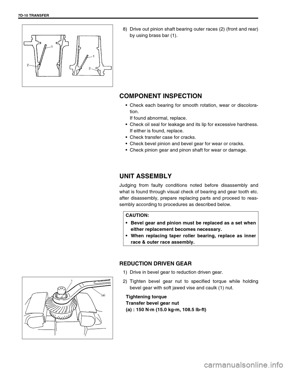
8) Drive out pinion shaft bearing outer races (2) (front and rear)
by using brass bar (1).
COMPONENT INSPECTION
Check each bearing for smooth rotation, wear or discolora-
tion.
If found abnormal, replace.
Check oil seal for leakage and its lip for excessive hardness.
If either is found, replace.
Check transfer case for cracks.
Check bevel pinion and bevel gear for wear or cracks.
Check pinion gear and pinon shaft for wear or damage.
UNIT ASSEMBLY
Judging from faulty conditions noted before disassembly and
what is found through visual check of bearing and gear tooth etc.
after disassembly, prepare replacing parts and proceed to reas-
sembly according to procedures as described below.
REDUCTION DRIVEN GEAR
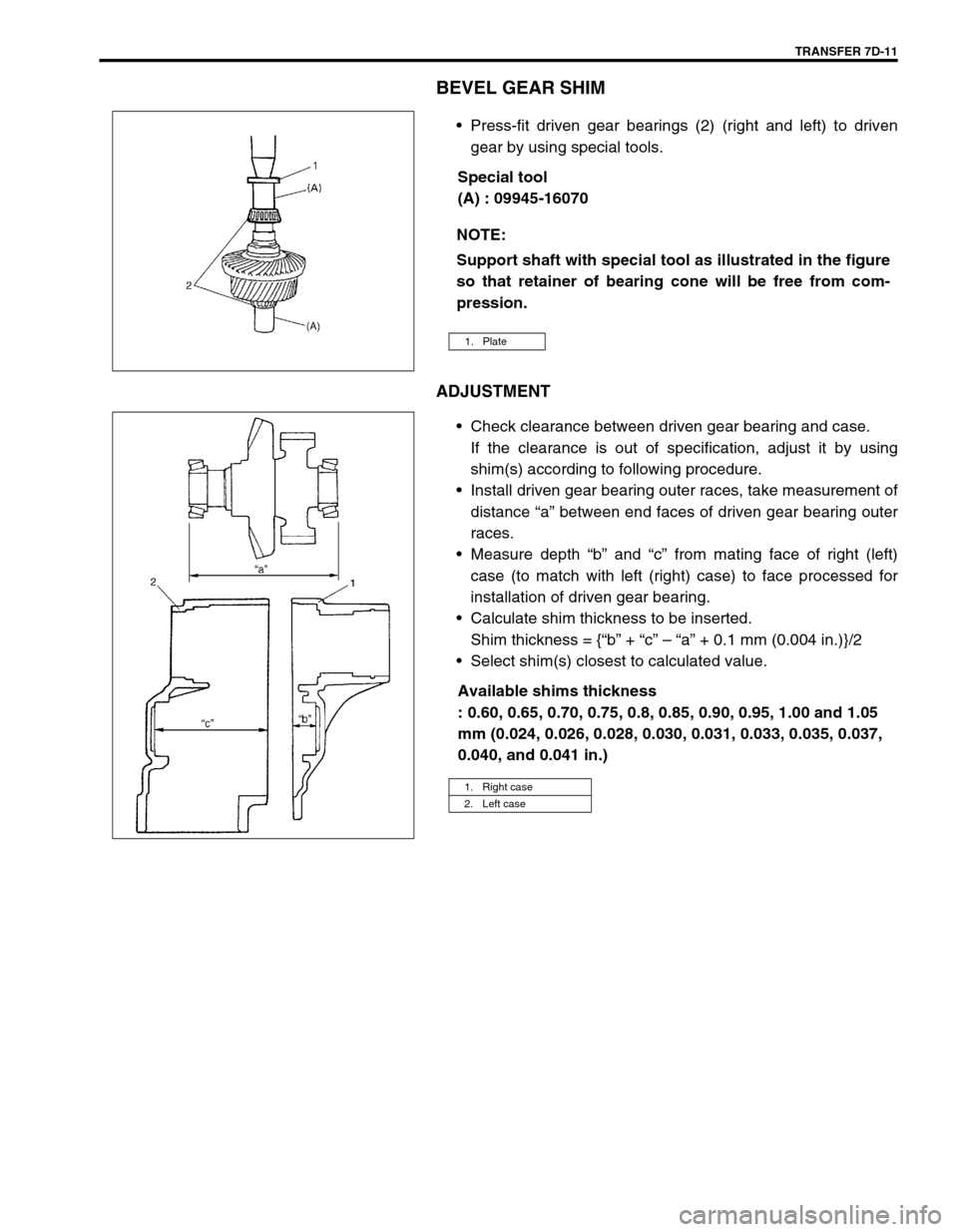
1) Drive in bevel gear to reduction driven gear.
2) Tighten bevel gear nut to specified torque while holding
bevel gear with soft jawed vise and caulk (1) nut.
Tightening torque
Transfer bevel gear nut
(a) : 150 N·m (15.0 kg-m, 108.5 lb-ft)
CAUTION:
Bevel gear and pinion must be replaced as a set when
either replacement becomes necessary.
When replacing taper roller bearing, replace as inner
race & outer race assembly.
Page 209 of 447

TRANSFER 7D-11
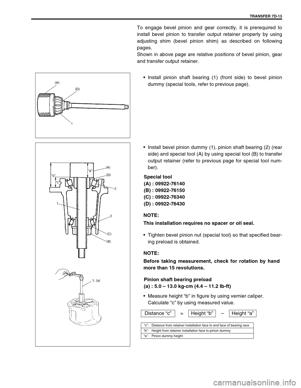
BEVEL GEAR SHIM
Press-fit driven gear bearings (2) (right and left) to driven
gear by using special tools.
Special tool
(A) : 09945-16070
ADJUSTMENT
Check clearance between driven gear bearing and case.
If the clearance is out of specification, adjust it by using
shim(s) according to following procedure.
Install driven gear bearing outer races, take measurement of
distance “a” between end faces of driven gear bearing outer
races.
Measure depth “b” and “c” from mating face of right (left)
case (to match with left (right) case) to face processed for
installation of driven gear bearing.
Calculate shim thickness to be inserted.
Shim thickness = {“b” + “c” – “a” + 0.1 mm (0.004 in.)}/2
Select shim(s) closest to calculated value.
Available shims thickness
: 0.60, 0.65, 0.70, 0.75, 0.8, 0.85, 0.90, 0.95, 1.00 and 1.05
mm (0.024, 0.026, 0.028, 0.030, 0.031, 0.033, 0.035, 0.037,
0.040, and 0.041 in.) NOTE:
Support shaft with special tool as illustrated in the figure
so that retainer of bearing cone will be free from com-
pression.
1. Plate
1. Right case
2. Left case
Page 210 of 447
7D-12 TRANSFER
TRANSFER OUTPUT RETAINER
ADJUSTMENT
Special tool
(A) : 09922-76140
(B) : 09922-76150
(C) : 09922-76340
(D) : 09922-76430
“a”: Pinion dummy (special tool) height 1. Transfer output retainer
“b”: Height from retainer installation face to pinion dummy 2. Left case
“c”: Distance from retainer installation face to end face of bearing race (“b” – “a”) 3. Pinion shaft bearing
“d”: Distance from end face of left case to cylinder section of reduction driven gear 4. Reduction driven gear
“e”: Outer diameter of cylinder section of reduction driven gear (29.7 mm/1.1693 in.) 5. Bevel pinion shaft
“f”: Distance from end face of left case to center shaft of reduction driven gear (“d” + “e”/2)
“g”: Dimension marked on bevel pinion shaft (Marked in shaft in mm)
“h”: Shim size for mounting distance adjustment (“g” + “c” – “f”)
Page 211 of 447

TRANSFER 7D-13
To engage bevel pinion and gear correctly, it is prerequired to
install bevel pinion to transfer output retainer properly by using
adjusting shim (bevel pinion shim) as described on following
pages.
Shown in above page are relative positions of bevel pinion, gear
and transfer output retainer.
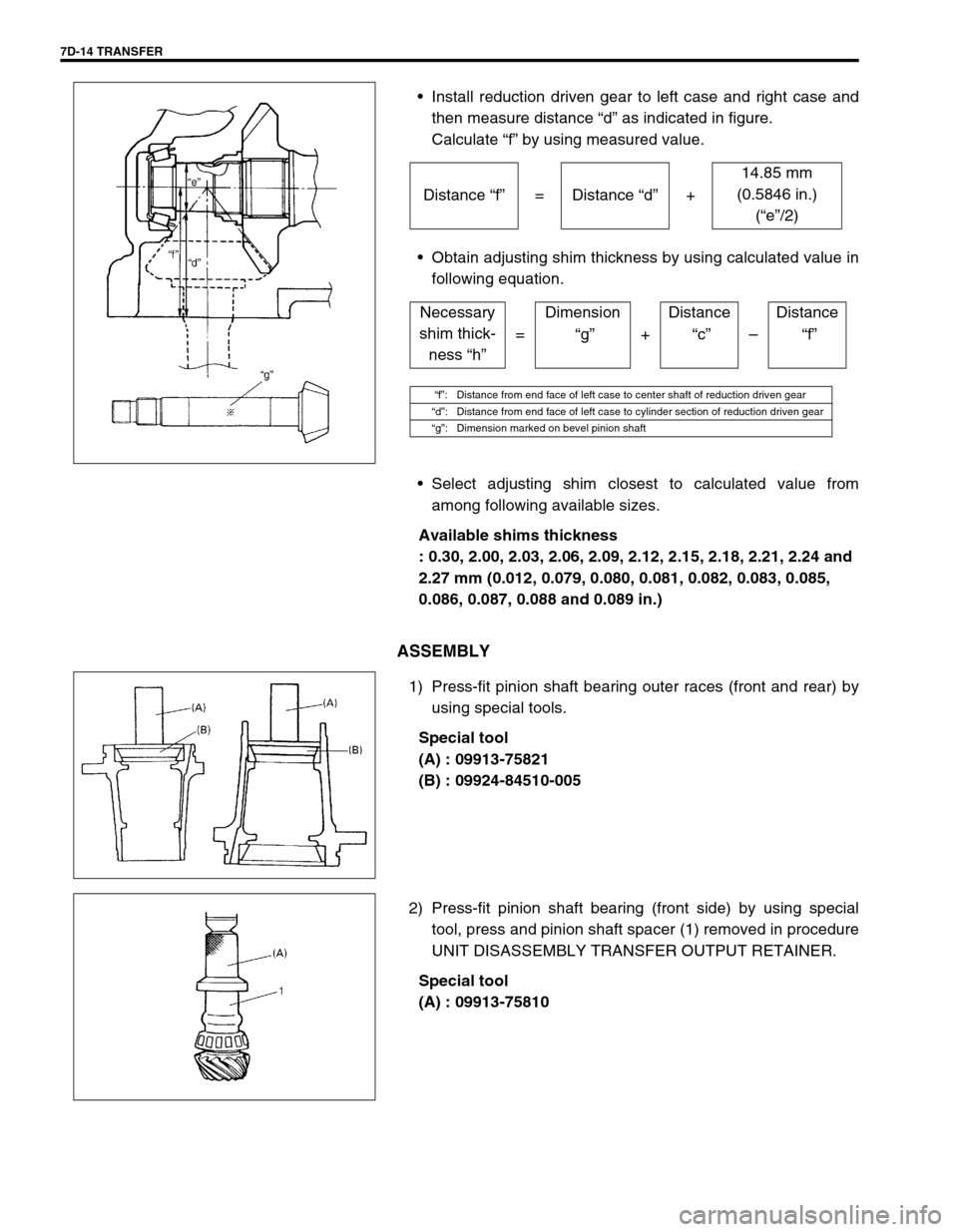
Install pinion shaft bearing (1) (front side) to bevel pinion
dummy (special tools, refer to previous page).
Install bevel pinion dummy (1), pinion shaft bearing (2) (rear
side) and special tool (A) by using special tool (B) to transfer
output retainer (refer to previous page for special tool num-
ber).
Special tool
(A) : 09922-76140
(B) : 09922-76150
(C) : 09922-76340
(D) : 09922-76430
Tighten bevel pinion nut (special tool) so that specified bear-
ing preload is obtained.
Pinion shaft bearing preload
(a) : 5.0 – 13.0 kg-cm (4.4 – 11.2 Ib-ft)
Measure height “b” in figure by using vernier caliper.
Calculate “c” by using measured value.
NOTE:
This installation requires no spacer or oil seal.
NOTE:
Before taking measurement, check for rotation by hand
more than 15 revolutions.
Distance “c”= Height “b”–Height “a”
“c”: Distance from retainer installation face to end face of bearing race
“b”: Height from retainer installation face to pinion dummy
“a”: Pinion dummy height
Page 212 of 447

7D-14 TRANSFER
Install reduction driven gear to left case and right case and
then measure distance “d” as indicated in figure.
Calculate “f” by using measured value.
Obtain adjusting shim thickness by using calculated value in
following equation.
Select adjusting shim closest to calculated value from
among following available sizes.
Available shims thickness
: 0.30, 2.00, 2.03, 2.06, 2.09, 2.12, 2.15, 2.18, 2.21, 2.24 and
2.27 mm (0.012, 0.079, 0.080, 0.081, 0.082, 0.083, 0.085,
0.086, 0.087, 0.088 and 0.089 in.)
ASSEMBLY
1) Press-fit pinion shaft bearing outer races (front and rear) by
using special tools.
Special tool
(A) : 09913-75821
(B) : 09924-84510-005
2) Press-fit pinion shaft bearing (front side) by using special
tool, press and pinion shaft spacer (1) removed in procedure
UNIT DISASSEMBLY TRANSFER OUTPUT RETAINER.
Special tool
(A) : 09913-7581014.85 mm
(0.5846 in.)
(“e”/2) Distance “f”= Distance “d”+
Necessary
shim thick-
ness “h”Dimension Distance Distance
= “g”+ “c”– “f”
“f”: Distance from end face of left case to center shaft of reduction driven gear
“d”: Distance from end face of left case to cylinder section of reduction driven gear
“g”: Dimension marked on bevel pinion shaft