Page 143 of 447
AUTOMATIC TRANSMISSION (4 A/T) 7B-101
4) Remove direct clutch balancer (1) and direct clutch return
spring seat (2).
5) Remove direct clutch piston (3).
Blow compressed air through input shaft oil hole to remove
piston. If piston does not pop out, take it out with long nose
pliers.
6) Remove D-ring (4) from direct clutch No.1 drum (5).
INSPECTION
Clutch Discs, Plates and Flange
Check that sliding surfaces of discs, plates and flanges are not
worn or burnt. If necessary, replace.
Direct Clutch Return Spring Seat
Measure height of direct clutch return spring.
Height of direct clutch return spring
: 16.3 mm (0.642 in.)
.
NOTE:
If disc lining is exfoliated or discolored, replace all
discs.
Before assembling new discs, soak them in A/T fluid
for at least two hours.
NOTE:
Do not apply excessive force when measuring spring
height.
Perform measurement at several points.
Page 144 of 447

7B-102 AUTOMATIC TRANSMISSION (4 A/T)
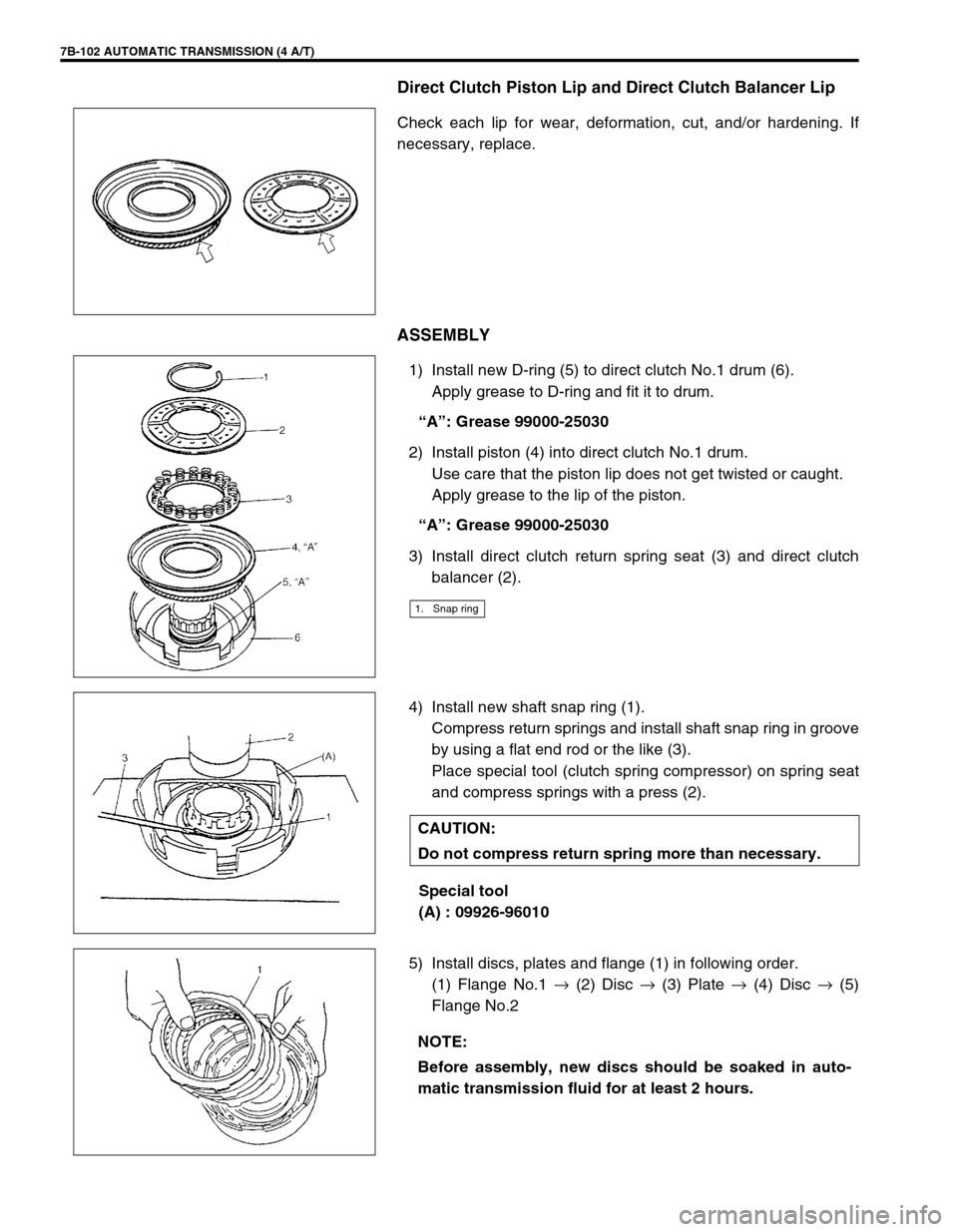
Direct Clutch Piston Lip and Direct Clutch Balancer Lip
Check each lip for wear, deformation, cut, and/or hardening. If
necessary, replace.
ASSEMBLY
1) Install new D-ring (5) to direct clutch No.1 drum (6).
Apply grease to D-ring and fit it to drum.
“A”: Grease 99000-25030
2) Install piston (4) into direct clutch No.1 drum.
Use care that the piston lip does not get twisted or caught.
Apply grease to the lip of the piston.
“A”: Grease 99000-25030
3) Install direct clutch return spring seat (3) and direct clutch
balancer (2).
4) Install new shaft snap ring (1).
Compress return springs and install shaft snap ring in groove
by using a flat end rod or the like (3).
Place special tool (clutch spring compressor) on spring seat
and compress springs with a press (2).
Special tool
(A) : 09926-96010
5) Install discs, plates and flange (1) in following order.
(1) Flange No.1 →
(2) Disc →
(3) Plate →
(4) Disc →
(5)
Flange No.2
1. Snap ring
CAUTION:
Do not compress return spring more than necessary.
NOTE:
Before assembly, new discs should be soaked in auto-
matic transmission fluid for at least 2 hours.
Page 154 of 447
7B-112 AUTOMATIC TRANSMISSION (4 A/T)
DIFFERENTIAL ASSEMBLY
Servicing procedure for differential assembly is similar to that for manual transmission. Refer to Section 7A of
this manual for adjustment procedure.
DISASSEMBLY
1) Remove R bearing and then speed sensor rotor using spe-
cial tool and puller.
Special tool
(A) : 09925-88210
2) Hold differential assembly with soft jawed vise, remove final
gear (1).
1. Differential pinion 7. Differential right side bearing (R bearing) 13. Pinion shaft pin
2. Differential gear
8. Speedometer sensor rotor Apply automatic transmission fluid.
3. Washer (for pinion)
9. Differential case Tightening torque
4. Pinion shaft
10. Final gear Do not reuse.
5. Washer (for gear) 11. Bolt
6. Differential side oil seal
: Apply grease 99000-25030 to oil seal lip.
12. Differential left side bearing (L bearing)
1. Differential gear assembly
Page 155 of 447

AUTOMATIC TRANSMISSION (4 A/T) 7B-113
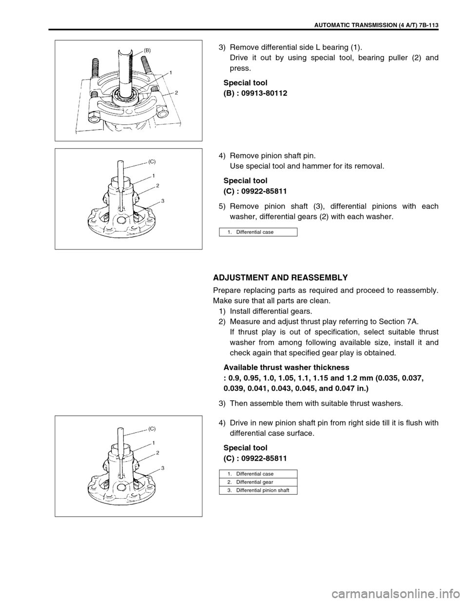
3) Remove differential side L bearing (1).
Drive it out by using special tool, bearing puller (2) and
press.
Special tool
(B) : 09913-80112
4) Remove pinion shaft pin.
Use special tool and hammer for its removal.
Special tool
(C) : 09922-85811
5) Remove pinion shaft (3), differential pinions with each
washer, differential gears (2) with each washer.
ADJUSTMENT AND REASSEMBLY
Prepare replacing parts as required and proceed to reassembly.
Make sure that all parts are clean.
1) Install differential gears.
2) Measure and adjust thrust play referring to Section 7A.
If thrust play is out of specification, select suitable thrust
washer from among following available size, install it and
check again that specified gear play is obtained.
Available thrust washer thickness
: 0.9, 0.95, 1.0, 1.05, 1.1, 1.15 and 1.2 mm (0.035, 0.037,
0.039, 0.041, 0.043, 0.045, and 0.047 in.)
3) Then assemble them with suitable thrust washers.
4) Drive in new pinion shaft pin from right side till it is flush with
differential case surface.
Special tool
(C) : 09922-85811
1. Differential case
1. Differential case
2. Differential gear
3. Differential pinion shaft
Page 156 of 447

7B-114 AUTOMATIC TRANSMISSION (4 A/T)
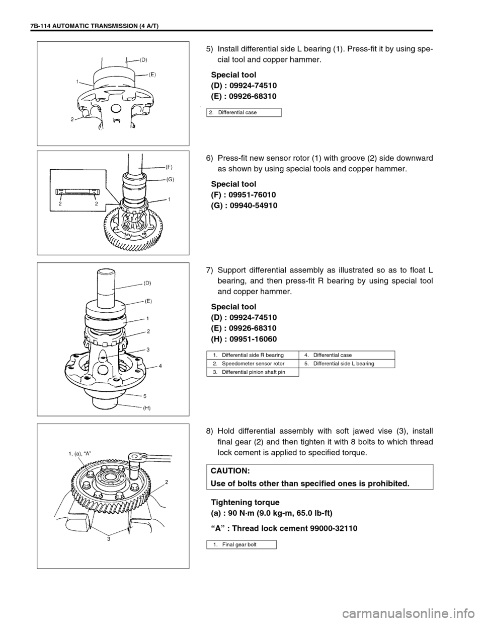
5) Install differential side L bearing (1). Press-fit it by using spe-
cial tool and copper hammer.
Special tool
(D) : 09924-74510
(E) : 09926-68310
.
6) Press-fit new sensor rotor (1) with groove (2) side downward
as shown by using special tools and copper hammer.
Special tool
(F) : 09951-76010
(G) : 09940-54910
7) Support differential assembly as illustrated so as to float L
bearing, and then press-fit R bearing by using special tool
and copper hammer.
Special tool
(D) : 09924-74510
(E) : 09926-68310
(H) : 09951-16060
8) Hold differential assembly with soft jawed vise (3), install
final gear (2) and then tighten it with 8 bolts to which thread
lock cement is applied to specified torque.
Tightening torque
(a) : 90 N·m (9.0 kg-m, 65.0 lb-ft)
“A” : Thread lock cement 99000-32110
2. Differential case
1. Differential side R bearing 4. Differential case
2. Speedometer sensor rotor 5. Differential side L bearing
3. Differential pinion shaft pin
CAUTION:
Use of bolts other than specified ones is prohibited.
1. Final gear bolt
Page 166 of 447
7B-124 AUTOMATIC TRANSMISSION (4 A/T)
22) Install thrust needle roller bearing (3).
23) Install thrust washer (2).
24) Install new gasket to transmission case and install rear cover
(1).
Tightening torque
Rear cover bolts
(a) : 19 N·m (1.9 kg-m, 14.0 lb-ft)
25) Measure clearance between thrust washer and rear cover in
the following manner.
Measure the shaft and play of planetary set (1) with dial
gauge (2).
If the obtained clearance is out of specification, select the
thrust washer from table below and repeat above steps 22) –
24) to obtain the clearance within specification.
Clearance between thrust washer and rear cover
Standard : 0.3 – 0.7 mm (0.012 – 0.028 in.)
Available thrust washer (thickness)
: 1.9 mm (0.075 in.), 2.2 mm (0.087 in.), 2.5 mm (0.098 in.)
or 2.8 mm (0.110 in.)
1. Rear cover
4. Gasket(a)
NOTE:
Install the hook (2) to the location shown in figure.
NOTE:
Make sure that tip of dial gauge is not in contact with
counter drive gear (3).
Page 167 of 447
AUTOMATIC TRANSMISSION (4 A/T) 7B-125
26) Attach parking lock rod (2) to manual shift shaft (1).
27) Install manual shift shaft and washer (3) to transmission
case. Fix manual shift shaft with washer, control shift lever
(4) and two nuts (5).
Apply grease to the washers.
Tightening torque
Control shift lever nuts
(a) : 30 N·m (3.0 kg-m, 22.0 lb-ft)
“A” : Grease 99000-25030
28) Install detent spring (1) to transmission case.
Tightening torque
Detent spring bolt (a) : 11 N·m (1.1 kg-m, 8.0 lb-ft)
29) Install thrust needle roller bearing (2) on counter bearing (3).
30) Install counter driven gear (1).
31) Install parking lock pawl sleeve (1) and oil plate (not shown
in figure).
Tightening torque
Parking lock pawl sleeve bolt
(a) : 19 N·m (1.9 kg-m, 14.0 lb-ft)
Page 168 of 447
7B-126 AUTOMATIC TRANSMISSION (4 A/T)
32) Install parking lock pawl (2).
33) Install parking lock pawl shaft (4), torsional spring (3), and
cover (1), then hold them with 2 bolts.
Tightening torque
Parking lock pawl bolts (a) : 11 N·m (1.1 kg-m, 8.0 lb-ft)
34) Install reverse brake (B2) plates, discs, flange and cushion
plate in following order :
(1) Cushion plate →
(2) Plate →
(3) Disc →
(4) Plate →
(5)
Disc →
(6) Plate →
(7) Disc →
(8) Plate →
(9) Disc →
(10)
Flange
35) Hold above parts with snap ring.
NOTE:
Note the direction of cushion plate (1).
Make sure that the plates are fitted into groove of
transmission case as shown in figure.
2. Brake plate side
3. Transmission case side