Page 175 of 698

3C-2 STEERING WHEEL AND COLUMN
GENERAL DESCRIPTION
STEERING COLUMN
This double tube type steering column has following three important features in addition to the steering function
:
The column is energy absorbing, designed to compress in a front-end collision.
The ignition switch and lock are mounted conveniently on this column.
With the column mounted lock, the ignition and steering operations can be locked to inhibit theft of the vehi-
cle.
To insure the energy absorbing action, it is important that only the specified screws, bolts, and nuts be used as
designated and that they are tightened to the specified torque.
When the column assembly is removed from the vehicle, special care must be taken in handling it. Use of a
steering wheel puller other than the one recommended in this manual or a sharp blow on the end of the steering
shaft, leaning on the assembly, or dropping the assembly could shear the plastic shear pins which maintain col-
umn length and position.
STEERING WHEEL AND DRIVER AIR BAG (INFLATOR) MODULE
The driver air bag (inflator) module is one of the supplemental restraint (air bag) system components and is
mounted to the center of the steering wheel. During certain frontal crashes, the air bag system supplements the
restraint of the driver’s and passenger’s seat belts by deploying the air bags.
The air bag (inflator) module should be handled with care to prevent accidental deployment. When servicing, be
sure to observe all WARNINGS and CAUTIONS and “SERVICE PRECAUTIONS” under “ON-VEHICLE SER-
VICE” in Section 10B.
DIAGNOSIS
For maintenance service of the steering wheel and column, refer to Section 0B.
For diagnosis of the steering wheel and column, refer to Section 3.
For diagnosis of the air bag system, refer to Section 10B.
INSPECTION AND REPAIR REQUIRED AFTER ACCIDENT
After an accident, whether the air bag has been deployed or not, be sure to perform checks, inspections and
repairs described under “CHECKING STEERING COLUMN ASSEMBLY AND LOWER SHAFT FOR ACCI-
DENT DAMAGE” as well as “REPAIRS AND INSPECTIONS REQUIRED AFTER ACCIDENT” under “DIAGNO-
SIS” in Section 10B.
Page 177 of 698
3C-4 STEERING WHEEL AND COLUMN
HANDLING AND STORAGE
For handling and storage, refer to “HANDLING AND STORAGE” under “SERVICE PRECAUTIONS” in Section
10B.
DISPOSAL
For disposal, refer to “DISPOSAL” under “SERVICE PRECAUTIONS” in Section 10B.
DRIVER AIR BAG (INFLATOR) MODULE
REMOVAL
1) Disconnect negative cable at battery.
2) Disable air bag system. Refer to “DISABLING AIR BAG
SYSTEM” under “SERVICE PRECAUTIONS” in Section
10B.
3) Loosen 2 bolts (1) mounting driver air bag (inflator) module
on its both side.
4) Remove driver air bag (inflator) module (3) from steering
wheel.
5) Disconnect yellow connector (1) of driver air bag (inflator)
module and horn connector (2) in order a) – d) shown in fig-
ure. WARNING:
When handling an air bag (inflator) module, be sure to
read “SERVICE PRECAUTIONS” in Section 10B and
observe each instruction. Failure to follow them could
cause a damage to the air bag (inflator) module or result
in personal injury.
Page 178 of 698

STEERING WHEEL AND COLUMN 3C-5
INSPECTION
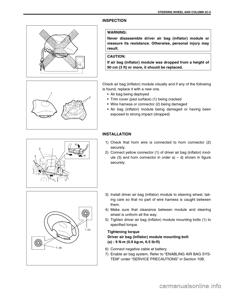
Check air bag (inflator) module visually and if any of the following
is found, replace it with a new one.
Air bag being deployed
Trim cover (pad surface) (1) being cracked
Wire harness or connector (2) being damaged
Air bag (inflator) module being damaged or having been
exposed to strong impact (dropped)
INSTALLATION
1) Check that horn wire is connected to horn connector (2)
securely.
2) Connect yellow connector (1) of driver air bag (inflator) mod-
ule (3) and horn connector in order a) – d) shown in figure
securely.
3) Install driver air bag (inflator) module to steering wheel, tak-
ing care so that no part of wire harness is caught between
them.
4) Make sure that clearance between module and steering
wheel is uniform all the way.
5) Tighten driver air bag (inflator) module mounting bolts (1) to
specified torque.
Tightening torque
Driver air bag (inflator) module mounting bolt
(a) : 9 N·m (0.9 kg-m, 6.5 lb-ft)
6) Connect negative cable at battery.
7) Enable air bag system. Refer to “ENABLING AIR BAG SYS-
TEM” under “SERVICE PRECAUTIONS” in Section 10B. WARNING:
Never disassemble driver air bag (inflator) module or
measure its resistance. Otherwise, personal injury may
result.
CAUTION:
If air bag (inflator) module was dropped from a height of
90 cm (3 ft) or more, it should be replaced.
Page 187 of 698

3C-14 STEERING WHEEL AND COLUMN
INSPECTION
INSTALLATION
1) Be sure that front wheels and steering wheel are in straight
forward state.
If steering lock assembly (ignition switch) is removed, install
it, referring to “STEERING LOCK ASSEMBLY (IGNITION
SWITCH)” in this section.
2) Align flat part “A” of steering lower shaft (1) with bolt hole “B”
of joint (2) of steering column as shown. Then insert steering
lower shaft (1) into shaft joint (2) of steering column with
matching marks (3) made before removal.
3) Install steering column and tighten steering column mounting
nuts (“A”, “B”) by hand.
4) Connect all connectors disconnected in REMOVAL.
Ignition switch
Combination switch
P/S control module (if equipped)
Horn
Immobilizer control module (if equipped) NOTE:
Vehicles involved in accidents resulting in body damage,
where steering column has been impacted (or air bag
deployed), may have a damaged or misaligned steering
column. For checking procedure of steering column
assembly, refer to “CHECKING STEERING COLUMN
ASSEMBLY AND LOWER SHAFT FOR ACCIDENT DAM-
AGE”.
CAUTION:
After tightening steering column mounting nuts, shaft
joint bolts should be tightened. Wrong tightening order
above could cause a damage to shaft joint.
Page 189 of 698
3C-16 STEERING WHEEL AND COLUMN
STEERING LOCK ASSEMBLY (IGNITION
SWITCH)
REMOVAL
1) Remove steering column (1). Refer to “STEERING COL-
UMN”.
2) Using center punch (1), loosen and remove steering lock
mounting bolts (2).
3) Turn ignition key to “ACC” or “ON” position and remove
steering lock assembly from steering column.
INSTALLATION
1) Position oblong hole (1) of steering shaft (2) in the center of
hole (3) in column (4).
2) Turn ignition key to “ACC” or “ON” position and install steer-
ing lock assembly (5) onto column (4).
3) Now turn ignition key to “LOCK” position and pull it out.
4) Align hub on lock with oblong hole (1) of steering shaft (2)
and rotate shaft to assure that steering shaft (4) is locked.
NOTE:
Use care not to damage aluminum part of steering lock
body with center punch.
Page 190 of 698

STEERING WHEEL AND COLUMN 3C-17
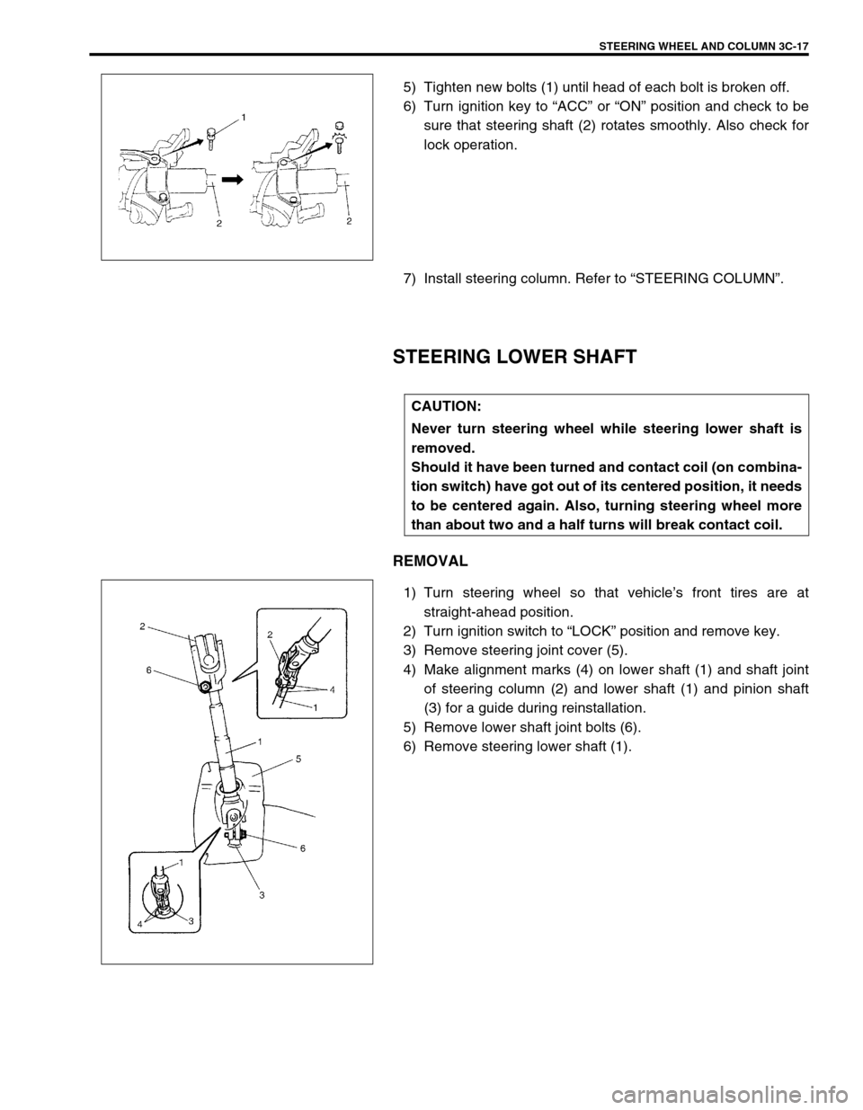
5) Tighten new bolts (1) until head of each bolt is broken off.
6) Turn ignition key to “ACC” or “ON” position and check to be
sure that steering shaft (2) rotates smoothly. Also check for
lock operation.
7) Install steering column. Refer to “STEERING COLUMN”.
STEERING LOWER SHAFT
REMOVAL
1) Turn steering wheel so that vehicle’s front tires are at
straight-ahead position.
2) Turn ignition switch to “LOCK” position and remove key.
3) Remove steering joint cover (5).
4) Make alignment marks (4) on lower shaft (1) and shaft joint
of steering column (2) and lower shaft (1) and pinion shaft
(3) for a guide during reinstallation.
5) Remove lower shaft joint bolts (6).
6) Remove steering lower shaft (1).
CAUTION:
Never turn steering wheel while steering lower shaft is
removed.
Should it have been turned and contact coil (on combina-
tion switch) have got out of its centered position, it needs
to be centered again. Also, turning steering wheel more
than about two and a half turns will break contact coil.
Page 199 of 698
3D-6 FRONT SUSPENSION
ON-VEHICLE SERVICE
STRUT ASSEMBLY
REMOVAL
1) Hoist vehicle, allowing front suspension to hang free.
2) Remove wheel.
3) Remove E-ring (1) securing brake hose and take brake hose
off strut bracket as shown.
4) Remove strut bracket bolts (2).
1. Strut assembly 5. Coil spring upper seat 9. Strut support nut
2. Coil spring 6. Strut bearing
: Apply grease (99000-25010) to all around bearing.10. Strut bracket bolt
: Insert from vehicle rear side.
3. Bump stopper 7. Strut support 11. Strut bracket nut
4. Coil spring lower seat 8. Strut nut Tightening torque
Page 201 of 698
3D-8 FRONT SUSPENSION
Tighten strut nut to specified torque by using special tools.
Tightening torque
Strut nut (a) : 50 N·m (5.0 kg-m, 36.5 lb-ft)
Special tool
(A) : 09900-00411
(B) : 09900-00414
(C) : 09945-26010
INSTALLATION
Install strut assembly by reversing removal procedure, noting the
following instructions.
Insert bolts in such direction as shown in figure.
Tighten all fasteners to specified torque.
Tightening torque
Strut bracket nut (a) : 105 N·m (10.5 kg-m, 76.0 lb-ft)
Strut support nut (b) : 23 N·m (2.3 kg-m, 17.0 lb-ft)
Tighten wheel nut to specified torque.
Tightening torque
Wheel nut : 85 N·m (8.5 kg-m, 61.5 lb-ft)
After installation, confirm front end (wheel) alignment refer-
ring to Section 3A.
NOTE:
Don’t twist brake hose when installing it.
Install E-ring (1) as far as it fits to bracket (2) as shown
in figure.