Page 613 of 698
6C-6 ENGINE FUEL
FUEL TANK INLET VALVE
REMOVAL
1) Remove fuel filler cap.
2) Insert hose of a hand operated pump into fuel filler hose (1)
and drain fuel in space “A” in the figure.
3) Hoist vehicle and remove clamp (2) and fuel filler hose (1)
from fuel tank.
4) Remove fuel tank inlet valve (1) using flat-bladed screw-
driver.
INSPECTION
Check fuel tank inlet valve for the followings.
Damage
Smooth opening and closing
If any damage or malfunction is found, replace.WARNING:
Refer to the WARNING at the beginning of ON-VEHICLE
SERVICE in this section.
CAUTION:
Do not force pump hose into fuel tank, or pump hose
may damage fuel tank inlet valve (2).
1
2
CAUTION:
Be careful not to damage fuel tank inlet valve (1) with flat-
bladed screwdriver.
Page 614 of 698

ENGINE FUEL 6C-7
INSTALLATION
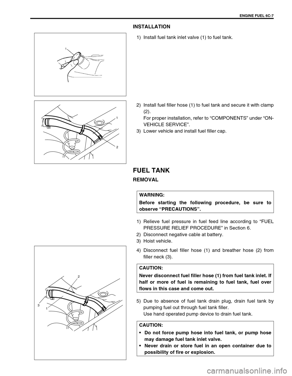
1) Install fuel tank inlet valve (1) to fuel tank.
2) Install fuel filler hose (1) to fuel tank and secure it with clamp
(2).
For proper installation, refer to “COMPONENTS” under “ON-
VEHICLE SERVICE”.
3) Lower vehicle and install fuel filler cap.
FUEL TANK
REMOVAL
1) Relieve fuel pressure in fuel feed line according to “FUEL
PRESSURE RELIEF PROCEDURE” in Section 6.
2) Disconnect negative cable at battery.
3) Hoist vehicle.
4) Disconnect fuel filler hose (1) and breather hose (2) from
filler neck (3).
5) Due to absence of fuel tank drain plug, drain fuel tank by
pumping fuel out through fuel tank filler.
Use hand operated pump device to drain fuel tank.
1
2
WARNING:
Before starting the following procedure, be sure to
observe “PRECAUTIONS”.
CAUTION:
Never disconnect fuel filler hose (1) from fuel tank inlet. If
half or more of fuel is remaining to fuel tank, fuel over
flows in this case and come out.
CAUTION:
Do not force pump hose into fuel tank, or pump hose
may damage fuel tank inlet valve.
Never drain or store fuel in an open container due to
possibility of fire or explosion.
2
1
3
Page 617 of 698
6C-10 ENGINE FUEL
5) Connect fuel feed hose (1) and vapor hose (2) to each pipe
as shown in figure and clamp them securely.
6) Connect negative cable at battery.
With engine OFF, turn ignition switch to ON position and
check for fuel leaks.
FUEL PUMP ASSEMBLY
REMOVAL
1) Remove fuel tank from vehicle. Refer to “FUEL TANK”.
2) Disconnect fuel breather hose (1), fuel vapor hose (2) and
pipes from fuel pump assembly.
When disconnecting joint of fuel feed line (3) from pipe,
unlock joint by inserting special tool between pipe and joint
lock first.
Special tool
(A) : 09919-47020 CAUTION:
When connecting joint, clean outside surfaces of pipe
where joint is to be inserted, push joint into pipe till
joint lock clicks and check to ensure that pipes are
connected securely, or fuel leak may occur.
Never let the fuel hoses touch the ABS sensor harness
(if equipped).
WARNING:
Refer to the PRECAUTIONS at the beginning of ON-VEHI-
CLE SERVICE.
1
23
Page 644 of 698

ENGINE AND EMISSION CONTROL SYSTEM 6E1-23
2) Turn OFF ignition switch and leave over 10 minutes as it is.
3) Fuel pressure should be felt at fuel feed hose (1) for about 2
seconds after ignition switch ON.
If fuel pressure is not felt, advance to “Diagnostic Flow Table
B-3”.
REMOVAL
Remove fuel tank from body according to procedure described in
Section 6C and remove fuel pump from fuel tank.
INSPECTION
Check fuel pump filter for evidence of dirt and contamination. If
present, clean and check for presence of dirt in fuel tank.
INSTALLATION
1) Install fuel pump to its bracket.
2) Install fuel pump to fuel tank and then install fuel tank to
body according to procedure described in Section 6C.
FUEL INJECTOR
ON-VEHICLE INSPECTION
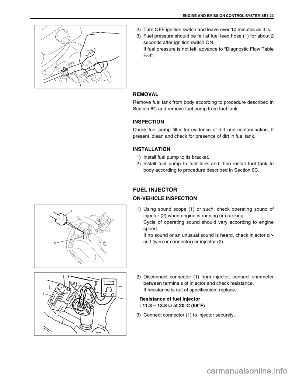
1) Using sound scope (1) or such, check operating sound of
injector (2) when engine is running or cranking.
Cycle of operating sound should vary according to engine
speed.
If no sound or an unusual sound is heard, check injector cir-
cuit (wire or connector) or injector (2).
2) Disconnect connector (1) from injector, connect ohmmeter
between terminals of injector and check resistance.
If resistance is out of specification, replace.
Resistance of fuel injector
: 11.3 – 13.8
Ω at 20°C (68°F)
3) Connect connector (1) to injector securely.