Page 300 of 698
BRAKES 5-27
b) For 4WD vehicle :
Pull brake drum off by using 8 mm bolts.
INSPECTION
Brake Drum
Inspect brake drum for wear.
If limit value of drum inner diameter is exceeded or uneven or
stepped wear is excessive, replace drum.
Drum inner diameter “a”
Standard : 180 mm (7.09 in.)
Limit : 182 mm (7.17 in.)
Brake Shoe
Measure thickness of brake shoe (1) (not including backing
metal). Also, check surface of lining for hardening, excessive
wear and oil.
Brake shoe thickness
Standard : 3.9 mm (0.15 in.)
Limit : 1.0 mm (0.04 in.)
NOTE:
When drum is removed, visually inspect wheel cylinder
for brake fluid leakage. Correct leaky point, if any.
CAUTION:
Never polish lining with sandpaper. If lining is polished
with sandpaper, hard particles of sandpaper will be
deposited in lining and may damage drum. When it is
required to correct lining, replace it with a new one.
Page 303 of 698
5-30 BRAKES
INSTALLATION
Install parts in reverse order of removal, noting the followings.
Install shoe hold down springs (2) by pushing them down in
place and turning hold down pins (1).
For procedure hereafter referring to “BRAKE DRUM”.
WHEEL CYLINDER
REMOVAL
1) Remove brake drum referring to “BRAKE DRUM”.
2) Remove break shoe referring to “BRAKE SHOE”.
3) Loosen brake pipe flare nut (1) but only within the extent that
fluid does not leak.
4) Remove wheel cylinder mounting bolts. Disconnect brake
pipe from wheel cylinder and put bleeder plug cap (1) onto
pipe to prevent fluid from spilling.
INSPECTION
Inspect wheel cylinder disassembled parts for wear, cracks, cor-
rosion or damage.
NOTE:
Clean wheel cylinder components with brake fluid.
Page 304 of 698

BRAKES 5-31
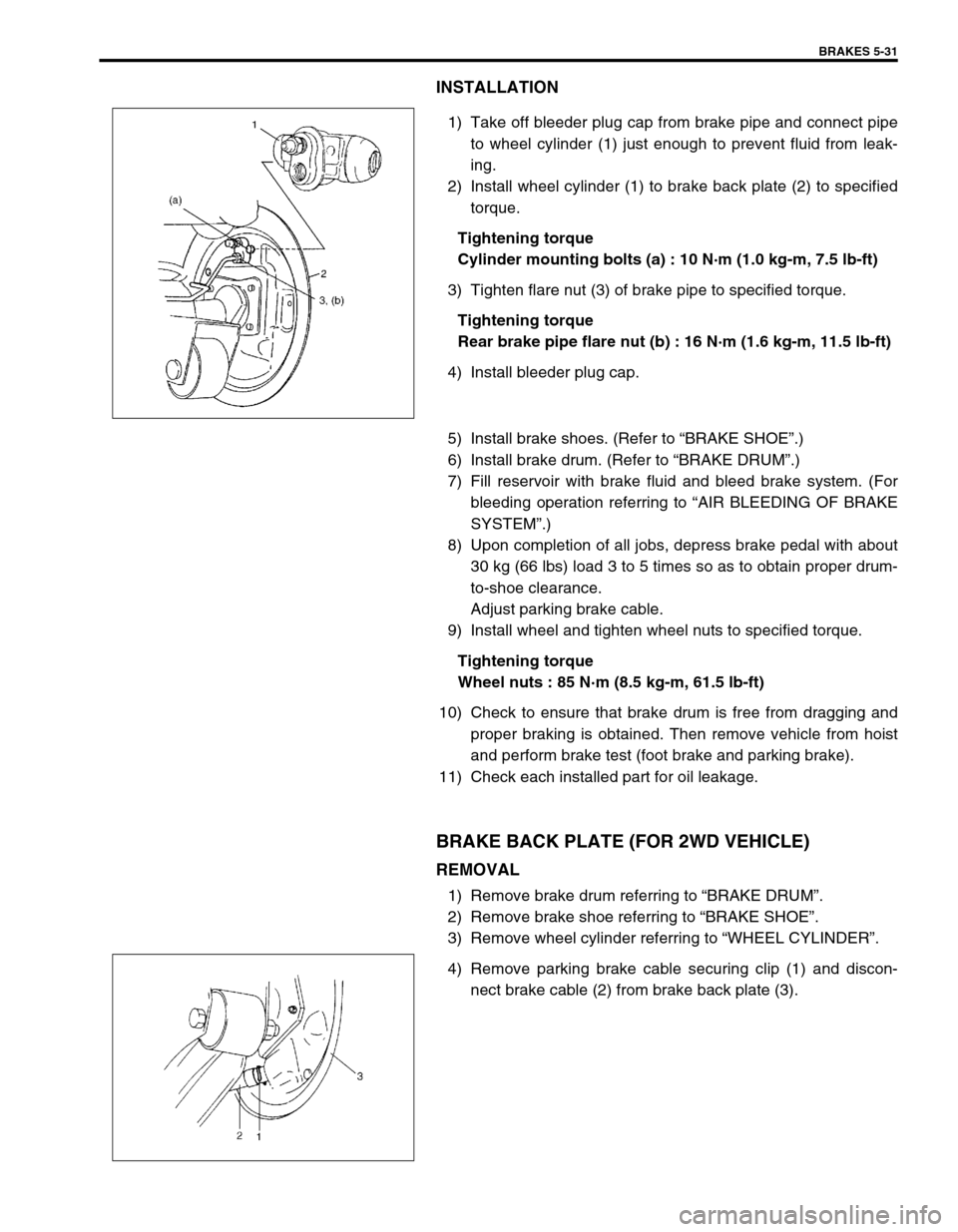
INSTALLATION
1) Take off bleeder plug cap from brake pipe and connect pipe
to wheel cylinder (1) just enough to prevent fluid from leak-
ing.
2) Install wheel cylinder (1) to brake back plate (2) to specified
torque.
Tightening torque
Cylinder mounting bolts (a) : 10 N·m (1.0 kg-m, 7.5 lb-ft)
3) Tighten flare nut (3) of brake pipe to specified torque.
Tightening torque
Rear brake pipe flare nut (b) : 16 N·m (1.6 kg-m, 11.5 lb-ft)
4) Install bleeder plug cap.
5) Install brake shoes. (Refer to “BRAKE SHOE”.)
6) Install brake drum. (Refer to “BRAKE DRUM”.)
7) Fill reservoir with brake fluid and bleed brake system. (For
bleeding operation referring to “AIR BLEEDING OF BRAKE
SYSTEM”.)
8) Upon completion of all jobs, depress brake pedal with about
30 kg (66 lbs) load 3 to 5 times so as to obtain proper drum-
to-shoe clearance.
Adjust parking brake cable.
9) Install wheel and tighten wheel nuts to specified torque.
Tightening torque
Wheel nuts : 85 N·m (8.5 kg-m, 61.5 lb-ft)
10) Check to ensure that brake drum is free from dragging and
proper braking is obtained. Then remove vehicle from hoist
and perform brake test (foot brake and parking brake).
11) Check each installed part for oil leakage.
BRAKE BACK PLATE (FOR 2WD VEHICLE)
REMOVAL
1) Remove brake drum referring to “BRAKE DRUM”.
2) Remove brake shoe referring to “BRAKE SHOE”.
3) Remove wheel cylinder referring to “WHEEL CYLINDER”.
4) Remove parking brake cable securing clip (1) and discon-
nect brake cable (2) from brake back plate (3).
Page 305 of 698
5-32 BRAKES
5) Remove brake back plate (1) by removing bolts (2).
INSTALLATION
1) Apply water tight sealant to mating surfaces of brake back
plate and rear axle.
“A” : Sealant 99000-31090
2) Install brake back plate and tighten back plate bolts to speci-
fied torque.
Tightening torque
Brake back plate bolts (a) : 23 N·m (2.3 kg-m, 17.0 lb-ft)
3) Apply water tight sealant where plate and cable contact, and
run parking brake cable (1) through brake back plate (2) and
secure it with clip (3).
“A” : Sealant 99000-31090
4) Install wheel cylinder, and tighten wheel cylinder bolts and
brake pipe flare nut to specified torque. (Refer to “WHEEL
CYLINDER”.)
5) For procedure hereafter referring to “WHEEL CYLINDER”.
A: Forward
Page 317 of 698
5-44 BRAKES
REAR BRAKE HOSE/PIPE
REMOVAL
1) Raise and support vehicle properly. Remove tire and wheel.
2) Clean dirt and foreign material from both flexible hose end and pipe end fittings.
3) Remove brake flexible hose or pipe.
INSTALLATION
Reverse brake flexible hose installation procedure, nothing the followings.
Fill and maintain brake fluid level in reservoir.
Bleed brake system. Refer to “AIR BLEEDING OF BRAKE SYSTEM”.
Perform brake test and check each installed part for fluid leakage.
Never reuse protector nut once removed. Be sure to use a new one.
Install clamps properly referring to figure below and tighten bolts.
When installing hose, make sure that it has no twist or kink.
Page 319 of 698
5-46 BRAKES
PARKING BRAKE CABLE
REMOVAL
1) Raise, suitably support vehicle and remove wheel.
2) Remove parking brake cable.
INSTALLATION
Install it by reversing removal procedure, noting the following points.
Install clamps properly referring to figure below.
Tighten bolts and nuts to specified torque.
Adjust parking brake cable. (Refer to “PARKING BRAKE INSPECTION AND ADJUSTMENT”.)
Check brake drum for dragging and brake system for proper performance. After removing vehicle from hoist,
brake test should be performed.
Page 361 of 698
5E-36 ANTILOCK BRAKE SYSTEM (ABS)
Reference
When using oscilloscope for this check, check if peak-to-peak
voltage (1) meets specification and waveform is complete.
Peak-to-peak voltage at 1/2 to 1 rotation per second
: 150 mV or more at 20 Hz
REMOVAL
1) Disconnect negative cable at battery.
2) Disconnect front wheel speed sensor coupler (1).
3) Hoist vehicle and remove wheel.
4) Remove harness clamp bolts (2) and grommet (3).
5) Remove front wheel speed sensor (4) from knuckle.
SENSOR INSPECTION
Check sensor for damage.
Check sensor for resistance and continuity.
Between both terminals (1) sensor
: 1.2 – 1.6 k
Ω
ΩΩ Ω at 20°C (68°F)
Between sensor terminal and sensor body (2)
: No continuity
If the check result is not as specified and any malcondition is
found, replace.
CAUTION:
Do not pull wire harness when removing front wheel
speed sensor.
Do not cause damage to surface of front wheel speed
sensor and do not allow dust, etc. to enter its installa-
tion hole.
Page 566 of 698

ENGINE MECHANICAL (M13 ENGINE) 6A1-65
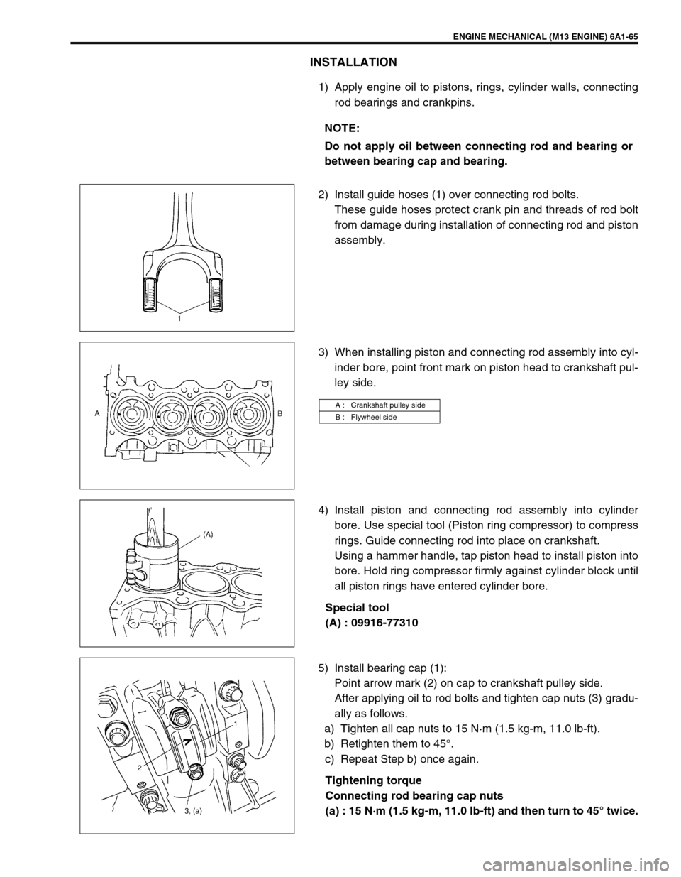
INSTALLATION
1) Apply engine oil to pistons, rings, cylinder walls, connecting
rod bearings and crankpins.
2) Install guide hoses (1) over connecting rod bolts.
These guide hoses protect crank pin and threads of rod bolt
from damage during installation of connecting rod and piston
assembly.
3) When installing piston and connecting rod assembly into cyl-
inder bore, point front mark on piston head to crankshaft pul-
ley side.
4) Install piston and connecting rod assembly into cylinder
bore. Use special tool (Piston ring compressor) to compress
rings. Guide connecting rod into place on crankshaft.
Using a hammer handle, tap piston head to install piston into
bore. Hold ring compressor firmly against cylinder block until
all piston rings have entered cylinder bore.
Special tool
(A) : 09916-77310
5) Install bearing cap (1):
Point arrow mark (2) on cap to crankshaft pulley side.
After applying oil to rod bolts and tighten cap nuts (3) gradu-
ally as follows.
a) Tighten all cap nuts to 15 N·m (1.5 kg-m, 11.0 lb-ft).
b) Retighten them to 45°.
c) Repeat Step b) once again.
Tightening torque
Connecting rod bearing cap nuts
(a) : 15 N·m (1.5 kg-m, 11.0 lb-ft) and then turn to 45° twice. NOTE:
Do not apply oil between connecting rod and bearing or
between bearing cap and bearing.
A : Crankshaft pulley side
B : Flywheel side