Page 34 of 698
MAINTENANCE AND LUBRICATION 0B-5
MAINTENANCE SERVICE
ENGINE
DRIVE BELT
WATER PUMP AND GENERATOR DRIVE BELT INSPEC-
TION
1) Disconnect negative (–) cable at battery.
2) Inspect belt for cracks, cuts, deformation, wear and cleanli-
ness. If any defect exists, replace.
Check belt for tension.
Water pump and generator belt tension
“a” : 4.5 - 5.5 mm (0.18 - 0.22 in.) deflection under 100 N
(10 kg, 22 lb) pressure
3) If belt is too tight or too loose, adjust it to specification by
adjusting alternator position.
4) Tighten alternator adjusting bolts and pivot bolt.
5) Connect negative (–) cable to battery.
WATER PUMP AND GENERATOR DRIVE BELT REPLACE-
MENT
Replace belt with new one referring to “WATER PUMP BELT” in
Section 6B.WARNING:
All inspection and replacement are to be performed with
ENGINE NOT RUNNING.
NOTE:
When replacing belt with a new one, adjust belt tension
to 3 - 4 mm (0.12 - 0.16 in.)
Page 40 of 698
MAINTENANCE AND LUBRICATION 0B-11
4) Install air cleaner filter fitting protrusion (1) of filter into
groove (2) of case and clamp upper case securely.
REPLACEMENT
Replace air cleaner filter with new one according to steps 1), 2)
and 4) of inspection procedure.
FUEL LINES AND CONNECTIONS
INSPECTION
Visually inspect fuel lines and connections for evidence of fuel
leakage, hose cracking and damage. Make sure all clamps are
secure.
Repair leaky joints, if any.
Replace hoses that are suspected of being cracked.
FUEL FILTER
REPLACEMENT
Fuel filter (1) is installed in fuel pump assembly (2) in fuel tank.
Replace fuel filter with new one, referring to “FUEL PUMP
ASSEMBLY” in Section 6C for proper procedure.
WARNING:
This work must be performed in a well ventilated area
and away from any open flames (such as gas hot water
heaters).
Page 391 of 698

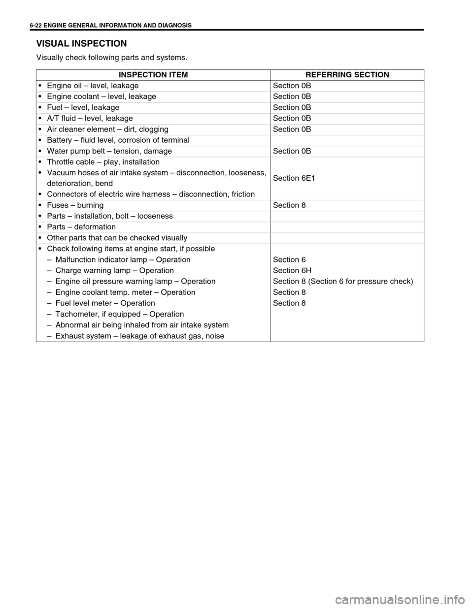
6-22 ENGINE GENERAL INFORMATION AND DIAGNOSIS
VISUAL INSPECTION
Visually check following parts and systems.
INSPECTION ITEM REFERRING SECTION
Engine oil – level, leakage Section 0B
Engine coolant – level, leakage Section 0B
Fuel – level, leakage Section 0B
A/T fluid – level, leakage Section 0B
Air cleaner element – dirt, clogging Section 0B
Battery – fluid level, corrosion of terminal
Water pump belt – tension, damage Section 0B
Throttle cable – play, installation
Section 6E1 Vacuum hoses of air intake system – disconnection, looseness,
deterioration, bend
Connectors of electric wire harness – disconnection, friction
Fuses – burning Section 8
Parts – installation, bolt – looseness
Parts – deformation
Other parts that can be checked visually
Check following items at engine start, if possible
–Malfunction indicator lamp – Operation Section 6
–Charge warning lamp – Operation Section 6H
–Engine oil pressure warning lamp – Operation Section 8 (Section 6 for pressure check)
–Engine coolant temp. meter – Operation Section 8
–Fuel level meter – Operation Section 8
–Tachometer, if equipped – Operation
–Abnormal air being inhaled from air intake system
–Exhaust system – leakage of exhaust gas, noise
Page 396 of 698

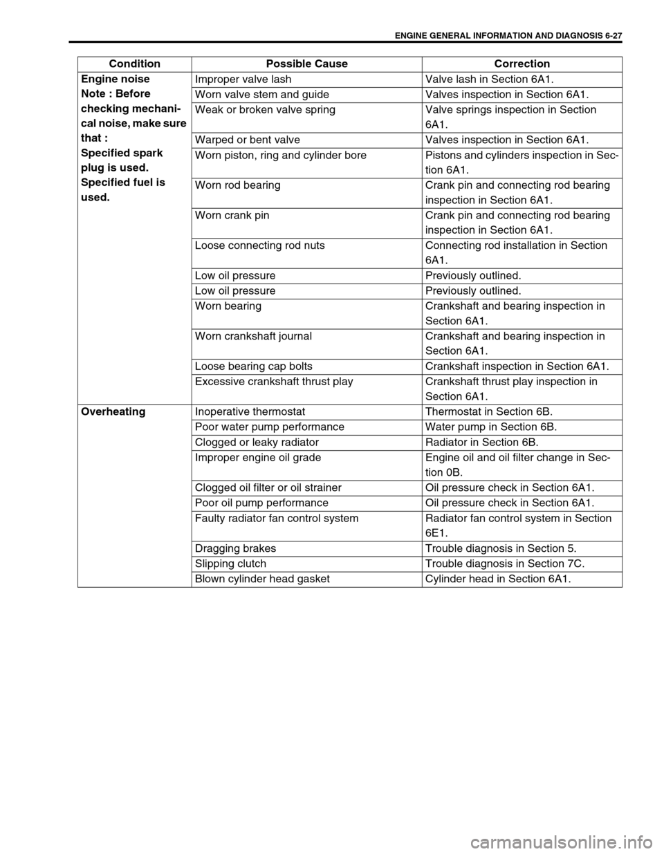
ENGINE GENERAL INFORMATION AND DIAGNOSIS 6-27
Engine noise
Note : Before
checking mechani-
cal noise, make sure
that :
Specified spark
plug is used.
Specified fuel is
used.Improper valve lash Valve lash in Section 6A1.
Worn valve stem and guide Valves inspection in Section 6A1.
Weak or broken valve spring Valve springs inspection in Section
6A1.
Warped or bent valve Valves inspection in Section 6A1.
Worn piston, ring and cylinder bore Pistons and cylinders inspection in Sec-
tion 6A1.
Worn rod bearing Crank pin and connecting rod bearing
inspection in Section 6A1.
Worn crank pin Crank pin and connecting rod bearing
inspection in Section 6A1.
Loose connecting rod nuts Connecting rod installation in Section
6A1.
Low oil pressure Previously outlined.
Low oil pressure Previously outlined.
Worn bearing Crankshaft and bearing inspection in
Section 6A1.
Worn crankshaft journal Crankshaft and bearing inspection in
Section 6A1.
Loose bearing cap bolts Crankshaft inspection in Section 6A1.
Excessive crankshaft thrust play Crankshaft thrust play inspection in
Section 6A1.
Overheating
Inoperative thermostat Thermostat in Section 6B.
Poor water pump performance Water pump in Section 6B.
Clogged or leaky radiator Radiator in Section 6B.
Improper engine oil grade Engine oil and oil filter change in Sec-
tion 0B.
Clogged oil filter or oil strainer Oil pressure check in Section 6A1.
Poor oil pump performance Oil pressure check in Section 6A1.
Faulty radiator fan control system Radiator fan control system in Section
6E1.
Dragging brakes Trouble diagnosis in Section 5.
Slipping clutch Trouble diagnosis in Section 7C.
Blown cylinder head gasket Cylinder head in Section 6A1. Condition Possible Cause Correction
Page 527 of 698
6A1-26 ENGINE MECHANICAL (M13 ENGINE)
3) Remove right side engine under cover (1).
4) Remove A/C compressor belt (3) (if equipped).
5) Remove water pump belt (1).
6) Remove water pump pulley (2).
7) Drain engine oil.
8) Remove crankshaft pulley bolt (2).
To lock crankshaft pulley (1), use special tool with it as
shown in figure.
Special tool
(A) : 09917-68221
9) Remove oil pan (1) referring to “OIL PAN AND OIL PUMP
STRAINER”.
10) Remove cylinder head cover referring to “CYLINDER HEAD
COVER”.
Page 530 of 698
ENGINE MECHANICAL (M13 ENGINE) 6A1-29
5) Install cylinder head cover referring to “CYLINDER HEAD
COVER”.
6) Install oil pan (1) referring to “OIL PAN AND OIL PUMP
STRAINER”.
7) Install crankshaft pulley (1). Tighten bolt (2) to specified
torque. To lock crankshaft pulley, use special tool with it as
shown in the figure.
Special tool
(A) : 09917-68221
Tightening torque
Crankshaft pulley bolt (a) : 150 N·m (15.0 kg-m, 108.5 lb-ft)
8) Adjust water pump belt tension referring to Section 0B for
adjusting procedure.
9) Adjust A/C compressor belt tension (if equipped) referring to
Section 1B for adjusting procedure.
10) Install right side engine under cover.
11) Connect disconnected electric lead wires securely.
12) Refill engine with engine oil.
13) Verify that there is no oil leakage and exhaust gas leakage at
each connection.
Page 539 of 698

6A1-38 ENGINE MECHANICAL (M13 ENGINE)
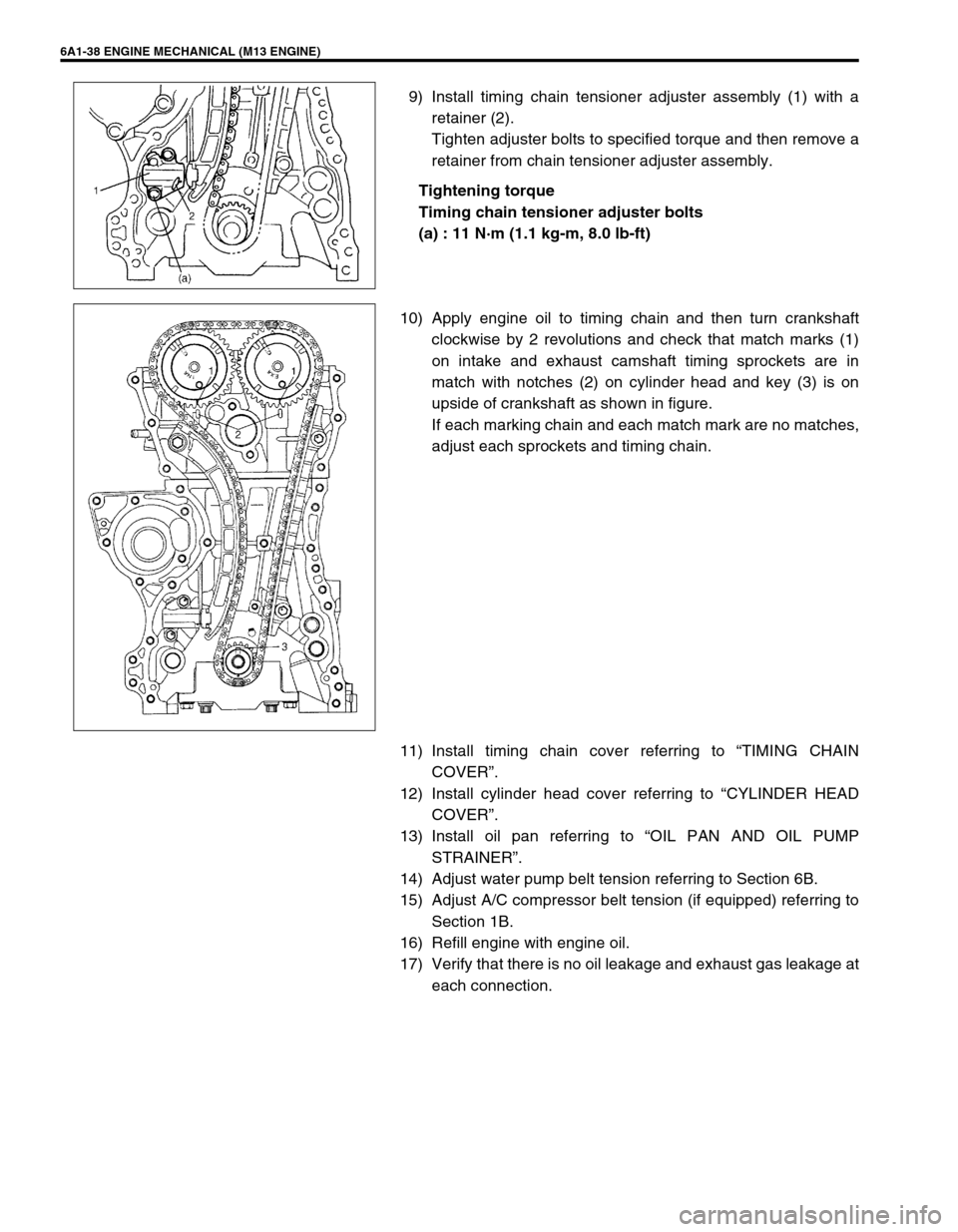
9) Install timing chain tensioner adjuster assembly (1) with a
retainer (2).
Tighten adjuster bolts to specified torque and then remove a
retainer from chain tensioner adjuster assembly.
Tightening torque
Timing chain tensioner adjuster bolts
(a) : 11 N·m (1.1 kg-m, 8.0 lb-ft)
10) Apply engine oil to timing chain and then turn crankshaft
clockwise by 2 revolutions and check that match marks (1)
on intake and exhaust camshaft timing sprockets are in
match with notches (2) on cylinder head and key (3) is on
upside of crankshaft as shown in figure.
If each marking chain and each match mark are no matches,
adjust each sprockets and timing chain.
11) Install timing chain cover referring to “TIMING CHAIN
COVER”.
12) Install cylinder head cover referring to “CYLINDER HEAD
COVER”.
13) Install oil pan referring to “OIL PAN AND OIL PUMP
STRAINER”.
14) Adjust water pump belt tension referring to Section 6B.
15) Adjust A/C compressor belt tension (if equipped) referring to
Section 1B.
16) Refill engine with engine oil.
17) Verify that there is no oil leakage and exhaust gas leakage at
each connection.
Page 544 of 698

ENGINE MECHANICAL (M13 ENGINE) 6A1-43
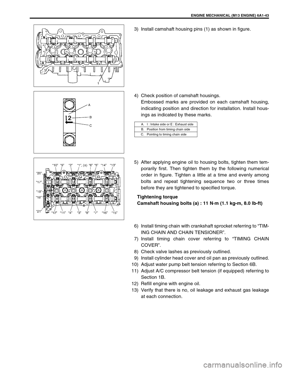
3) Install camshaft housing pins (1) as shown in figure.
4) Check position of camshaft housings.
Embossed marks are provided on each camshaft housing,
indicating position and direction for installation. Install hous-
ings as indicated by these marks.
5) After applying engine oil to housing bolts, tighten them tem-
porarily first. Then tighten them by the following numerical
order in figure. Tighten a little at a time and evenly among
bolts and repeat tightening sequence two or three times
before they are tightened to specified torque.
Tightening torque
Camshaft housing bolts (a) : 11 N·m (1.1 kg-m, 8.0 lb-ft)
6) Install timing chain with crankshaft sprocket referring to “TIM-
ING CHAIN AND CHAIN TENSIONER”.
7) Install timing chain cover referring to “TIMING CHAIN
COVER”.
8) Check valve lashes as previously outlined.
9) Install cylinder head cover and oil pan as previously outlined.
10) Adjust water pump belt tension referring to Section 6B.
11) Adjust A/C compressor belt tension (if equipped) referring to
Section 1B.
12) Refill engine with engine oil.
13) Verify that there is no, oil leakage and exhaust gas leakage
at each connection.
A. I : Intake side or E : Exhaust side
B. Position from timing chain side
C. Pointing to timing chain side