2000 NISSAN PATROL acceleration position sensor
[x] Cancel search: acceleration position sensorPage 8 of 1033
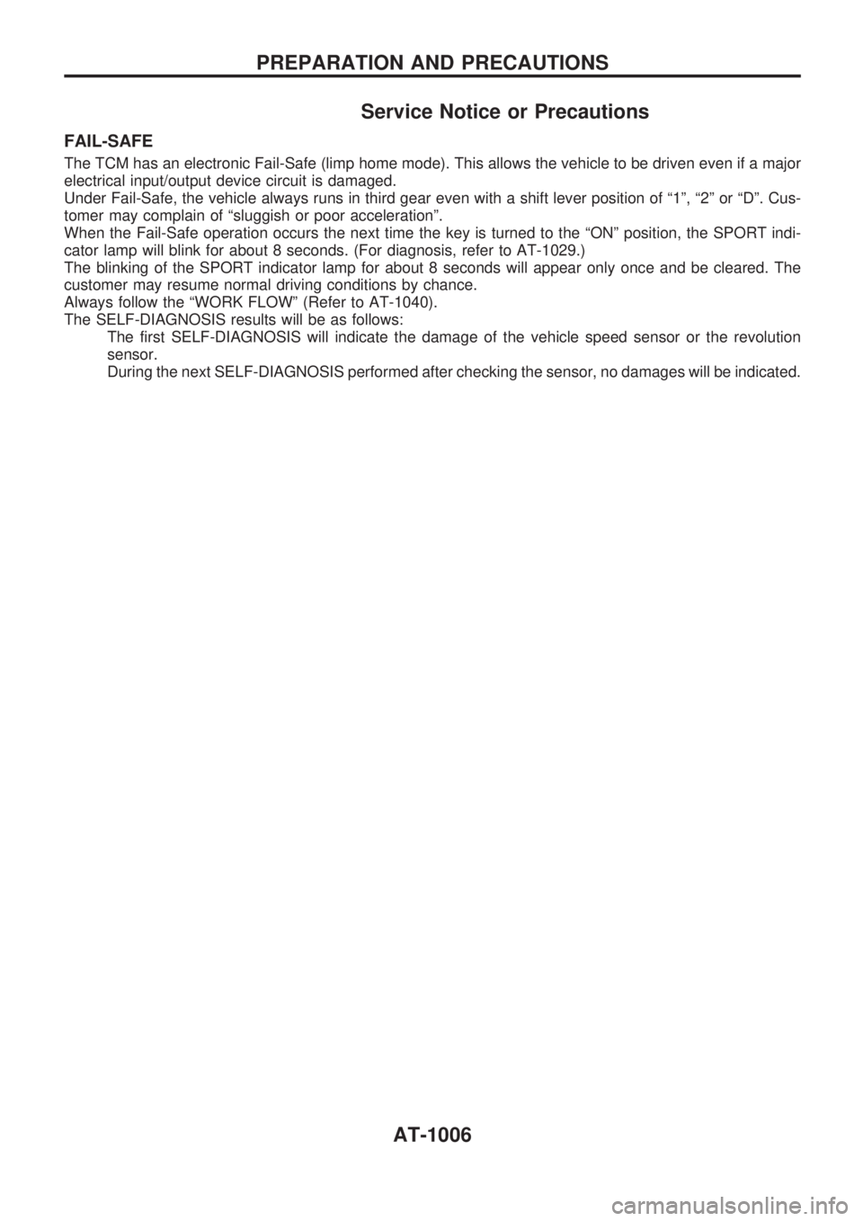
Service Notice or Precautions
FAIL-SAFE
The TCM has an electronic Fail-Safe (limp home mode). This allows the vehicle to be driven even if a major
electrical input/output device circuit is damaged.
Under Fail-Safe, the vehicle always runs in third gear even with a shift lever position of ª1º, ª2º or ªDº. Cus-
tomer may complain of ªsluggish or poor accelerationº.
When the Fail-Safe operation occurs the next time the key is turned to the ªONº position, the SPORT indi-
cator lamp will blink for about 8 seconds. (For diagnosis, refer to AT-1029.)
The blinking of the SPORT indicator lamp for about 8 seconds will appear only once and be cleared. The
customer may resume normal driving conditions by chance.
Always follow the ªWORK FLOWº (Refer to AT-1040).
The SELF-DIAGNOSIS results will be as follows:
The first SELF-DIAGNOSIS will indicate the damage of the vehicle speed sensor or the revolution
sensor.
During the next SELF-DIAGNOSIS performed after checking the sensor, no damages will be indicated.
PREPARATION AND PRECAUTIONS
AT-1006
Page 59 of 1033
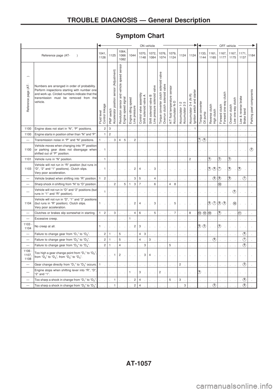
Symptom Chart
bON vehiclecbOFF vehiclec
Reference page (AT- )1041,
112611251064,
1066
108210441070,
11481072,
10841076,
10741079,
11241124 11241133,
11441161,
11651167,
11771167,
11751171,
11371184
Reference page (AT- )
Numbers are arranged in order of probability.
Perform inspections starting with number one
and work up. Circled numbers indicate that the
transmission must be removed from the
vehicle.
Fluid level
Control linkage
PNP switch
Accelerator position sensor (Adjustment)
Revolution sensor and vehicle speed sensor
Engine speed signal
Engine idling speed
Line pressure
Control valve assembly
Shift solenoid valve A
Shift solenoid valve B
Line pressure solenoid valve
Torque converter clutch solenoid valve
Overrun clutch solenoid valve
A/T fluid temperature sensor
Accumulator N-D
Accumulator 1-2
Accumulator 2-3
Accumulator 3-4 (N-R)
Ignition switch and starter
Torque converter
Oil pump
Reverse clutch
High clutch
Forward clutch
Forward one-way clutch
Overrun clutch
Low one-way clutch
Low & reverse brake
Brake band
Parking pawl components
1100 Engine does not start in ªNº, ªPº positions. . 2 3................1.......... .
1100 Engine starts in position other than ªNº and ªPº. . 1 2........................... .
Ð Transmission noise in ªPº and ªNº positions. 1 . . 3 45.2............
V7V6........ .
1100Vehicle moves when changing into ªPº position
or parking gear does not disengage when
shifted out of ªPº position..1............................
V2
1101 Vehicle runs in ªNº position. . 1................2...V4.V3.V5... .
1103Vehicle will not run in ªRº position (but runs in
ªDº, ª2º and ª1º positions). Clutch slips.
Very poor acceleration..1.....24..3..........
V5V6V7.V8.V9..
Ð Vehicle braked when shifting into ªRº position. 1 2.....35..4...........
V6V8.V9..V7.
Ð Sharp shock in shifting from ªNº to ªDº position. . .. 2 . 5137 . . 6 . . 48........
V10..... .
ÐVehicle will not run in ªDº and ª2º positions (but
runs in ª1º and ªRº position)..1.........................
V2.. .
1104Vehicle will not run in ªDº, ª1º and ª2º positions
(but runs in ªRº position). Clutch slips.
Very poor acceleration.1......24..3...5......
V6V7V8V9.V10.. .
Ð Clutches or brakes slip somewhat in starting. 12.3. . .46. .5. . .7. .8.
V13V12V10.V9...V11..
Ð Excessive creep.......1....................... .
1103 -
1104No creep at all. 1......23...........
V6V5..V4..... .
Ð Failure to change gear from ªD
1ºtoªD2º. .21.5...43...................V6.
Ð Failure to change gear from ªD
2ºtoªD3º. .21.5. . .4.3............V6.....V7.
Ð Failure to change gear from ªD
3ºtoªD4º. .21.4....3....5..............V6.
1106 -
1107,
1108Too high a gear change point from ªD
1ºtoªD2º,
from ªD2ºtoªD3º, from ªD3ºtoªD4º....12....34................... .
Ð Gear change directly from ªD
1ºtoªD3º occurs. 1...............2............V3.
ÐEngine stops when shifting lever into ªRº, ªDº,
ª2º and ª1º.......1.3. . .2.......
V4......... .
Ð Too sharp a shock in change from ªD
1ºtoªD2º....1...24.....5.3............V6.
Ð Too sharp a shock in change from ªD
2ºtoªD3º....1...24........3.....V5.....V6.
TROUBLE DIAGNOSIS Ð General Description
AT-1057
Page 60 of 1033
bON vehiclecbOFF vehiclec
Reference page (AT- )1041,
112611251064,
1066
108210441070,
11481072,
10841076,
10741079,
11241124 11241133,
11441161,
11651167,
11771167,
11751171,
11371184
Reference page (AT- )
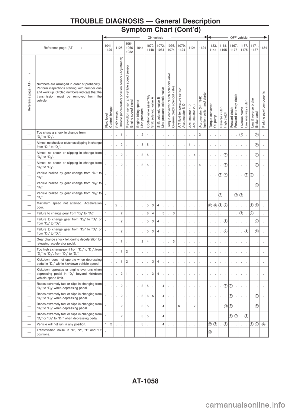
Numbers are arranged in order of probability.
Perform inspections starting with number one
and work up. Circled numbers indicate that the
transmission must be removed from the
vehicle.
Fluid level
Control linkage
PNP switch
Throttle (accelerator) position sensor (Adjustment)
Revolution sensor and vehicle speed sensor
Engine speed signal
Engine idling speed
Line pressure
Control valve assembly
Shift solenoid valve A
Shift solenoid valve B
Line pressure solenoid valve
Torque converter clutch solenoid valve
Overrun clutch solenoid valve
A/T fluid temperature sensor
Accumulator N-D
Accumulator 1-2
Accumulator 2-3
Accumulator 3-4 (N-R)
Ignition switch and starter
Torque converter
Oil pump
Reverse clutch
High clutch
Forward clutch
Forward one-way clutch
Overrun clutch
Low one-way clutch
Low & reverse brake
Brake band
Parking pawl components
ÐToo sharp a shock in change from
ªD3ºtoªD4º....1...24.........3.......V6..V5.
ÐAlmost no shock or clutches slipping in change
from ªD
1ºtoªD2º.1..2...35.......4............V6.
ÐAlmost no shock or slipping in change from
ªD
2ºtoªD3º.1..2...35........4.....V6.....V7.
ÐAlmost no shock or slipping in change from
ªD
3ºtoªD4º.1..2...35.........4....V6.....V7.
ÐVehicle braked by gear change from ªD
1ºto
ªD2º.1.....................V2V4...V5V3..
ÐVehicle braked by gear change from ªD
2ºto
ªD3º.1............................V2.
ÐVehicle braked by gear change from ªD
3ºto
ªD4º.1.....................V4..V3V2... .
ÐMaximum speed not attained. Acceleration
poor.1.2.....534.........
V11V10V6V7....V9V8.
Ð Failure to change gear from ªD
4ºtoªD3º. 1..2....64.5.3............V8.V7..
ÐFailure to change gear from ªD
3ºtoªD2ºor
from ªD4ºtoªD2º.1..2....534............V6.....V7.
ÐFailure to change gear from ªD
2ºtoªD1ºor
from ªD3ºtoªD1º.1..2....534............V7...V6.V8.
ÐGear change shock felt during deceleration by
releasing accelerator pedal....1...24....3................ .
ÐToo high a change point from ªD
4ºtoªD3º, from
ªD3ºtoªD2º, from ªD2ºtoªD1º....12......................... .
ÐKickdown does not operate when depressing
pedal in ªD
4º within kickdown vehicle speed....12....34................... .
ÐKickdown operates or engine overruns when
depressing pedal in ªD
4º beyond kickdown
vehicle speed limit....21....34................... .
ÐRaces extremely fast or slips in changing from
ªD
4ºtoªD3º when depressing pedal.1..2...35..4...........V6V7..... .
ÐRaces extremely fast or slips in changing from
ªD
4ºtoªD2º when depressing pedal.1..2...365.4............V8....V7.
ÐRaces extremely fast or slips in changing from
ªD
3ºtoªD2º when depressing pedal.1..2...35..4..6..7.....V10V9....V8.
ÐRaces extremely fast or slips in changing from
ªD
4ºorªD3ºtoªD1º when depressing pedal.1..2...35..4............V6V7.V8.. .
Ð Vehicle will not run in any position. 1 2.....3...4........
V9V5.V6....V8V7V10
ÐTransmission noise in ªDº, ª2º, ª1º and ªRº
positions.1...................V2......... .
TROUBLE DIAGNOSIS Ð General Description
Symptom Chart (Cont'd)
AT-1058
Page 254 of 1033
Fuel Injection Timing Control System
DESCRIPTION
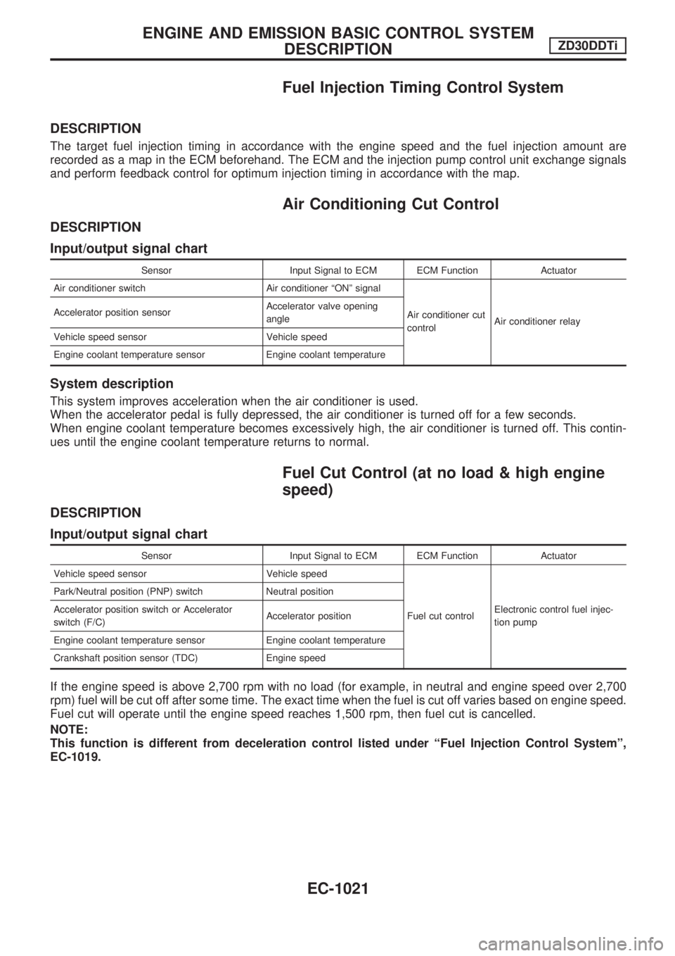
The target fuel injection timing in accordance with the engine speed and the fuel injection amount are
recorded as a map in the ECM beforehand. The ECM and the injection pump control unit exchange signals
and perform feedback control for optimum injection timing in accordance with the map.
Air Conditioning Cut Control
DESCRIPTION
Input/output signal chart
Sensor Input Signal to ECM ECM Function Actuator
Air conditioner switch Air conditioner ªONº signal
Air conditioner cut
controlAir conditioner relay Accelerator position sensorAccelerator valve opening
angle
Vehicle speed sensor Vehicle speed
Engine coolant temperature sensor Engine coolant temperature
System description
This system improves acceleration when the air conditioner is used.
When the accelerator pedal is fully depressed, the air conditioner is turned off for a few seconds.
When engine coolant temperature becomes excessively high, the air conditioner is turned off. This contin-
ues until the engine coolant temperature returns to normal.
Fuel Cut Control (at no load & high engine
speed)
DESCRIPTION
Input/output signal chart
Sensor Input Signal to ECM ECM Function Actuator
Vehicle speed sensor Vehicle speed
Fuel cut controlElectronic control fuel injec-
tion pump Park/Neutral position (PNP) switch Neutral position
Accelerator position switch or Accelerator
switch (F/C)Accelerator position
Engine coolant temperature sensor Engine coolant temperature
Crankshaft position sensor (TDC) Engine speed
If the engine speed is above 2,700 rpm with no load (for example, in neutral and engine speed over 2,700
rpm) fuel will be cut off after some time. The exact time when the fuel is cut off varies based on engine speed.
Fuel cut will operate until the engine speed reaches 1,500 rpm, then fuel cut is cancelled.
NOTE:
This function is different from deceleration control listed under ªFuel Injection Control Systemº,
EC-1019.
ENGINE AND EMISSION BASIC CONTROL SYSTEM
DESCRIPTIONZD30DDTi
EC-1021
Page 292 of 1033
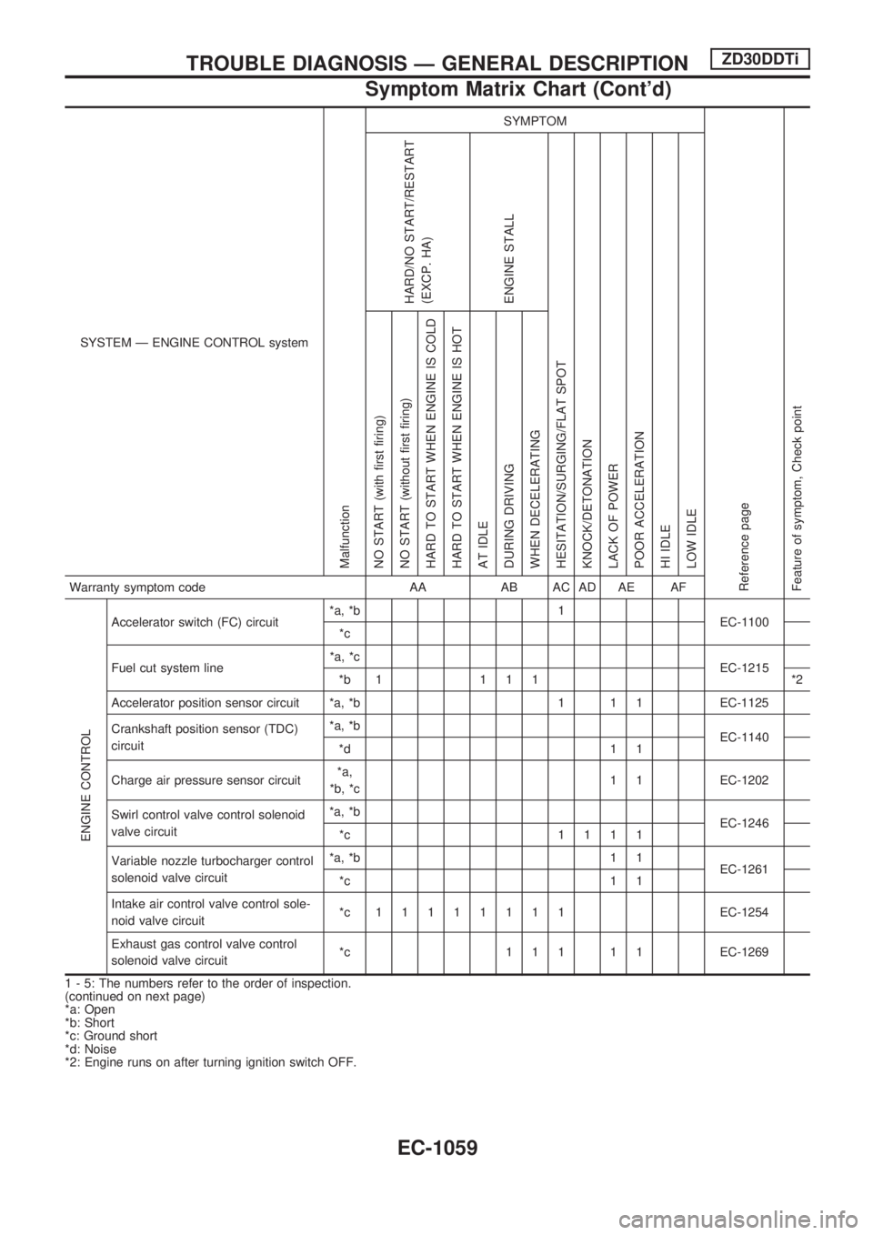
SYSTEM Ð ENGINE CONTROL system
Malfunction
SYMPTOM
Reference page
Feature of symptom, Check pointHARD/NO START/RESTART
(EXCP. HA)
ENGINE STALL
HESITATION/SURGING/FLAT SPOT
KNOCK/DETONATION
LACK OF POWER
POOR ACCELERATION
HI IDLE
LOW IDLE NO START (with first firing)
NO START (without first firing)
HARD TO START WHEN ENGINE IS COLD
HARD TO START WHEN ENGINE IS HOT
AT IDLE
DURING DRIVING
WHEN DECELERATINGWarranty symptom code AA AB AC AD AE AF
ENGINE CONTROL
Accelerator switch (FC) circuit*a, *b 1
EC-1100
*c
Fuel cut system line*a, *c
EC-1215
*b 1 1 1 1 *2
Accelerator position sensor circuit *a, *b 1 1 1 EC-1125
Crankshaft position sensor (TDC)
circuit*a, *b
EC-1140
*d 1 1
Charge air pressure sensor circuit*a,
*b, *c1 1 EC-1202
Swirl control valve control solenoid
valve circuit*a, *b
EC-1246
*c 1111
Variable nozzle turbocharger control
solenoid valve circuit*a, *b 1 1
EC-1261
*c 1 1
Intake air control valve control sole-
noid valve circuit*c 11111111EC-1254
Exhaust gas control valve control
solenoid valve circuit*c 1 1 1 1 1 EC-1269
1 - 5: The numbers refer to the order of inspection.
(continued on next page)
*a: Open
*b: Short
*c: Ground short
*d: Noise
*2: Engine runs on after turning ignition switch OFF.
TROUBLE DIAGNOSIS Ð GENERAL DESCRIPTIONZD30DDTi
Symptom Matrix Chart (Cont'd)
EC-1059
Page 294 of 1033
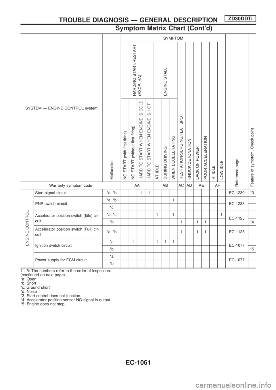
SYSTEM Ð ENGINE CONTROL system
Malfunction
SYMPTOM
Reference page
Feature of symptom, Check pointHARD/NO START/RESTART
(EXCP. HA)
ENGINE STALL
HESITATION/SURGING/FLAT SPOT
KNOCK/DETONATION
LACK OF POWER
POOR ACCELERATION
HI IDLE
LOW IDLE NO START (with first firing)
NO START (without first firing)
HARD TO START WHEN ENGINE IS COLD
HARD TO START WHEN ENGINE IS HOT
AT IDLE
DURING DRIVING
WHEN DECELERATINGWarranty symptom code AA AB AC AD AE AF
ENGINE CONTROL
Start signal circuit *a, *b 1 1 EC-1230 *3
PNP switch circuit*a, *b 1
EC-1233
*c
Accelerator position switch (Idle) cir-
cuit*a, *c 1 1 1
EC-1125
*b 1 1 1 *4
Accelerator position switch (Full) cir-
cuit*a, *b 1 1 1 EC-1125
Ignition switch circuit*a 1 111
EC-1077
*b*5
Power supply for ECM circuit*a
EC-1077
*b
1 - 5: The numbers refer to the order of inspection.
(continued on next page)
*a: Open
*b: Short
*c: Ground short
*d: Noise
*3: Start control does not function.
*4: Accelerator position sensor NG signal is output.
*5: Engine does not stop.
TROUBLE DIAGNOSIS Ð GENERAL DESCRIPTIONZD30DDTi
Symptom Matrix Chart (Cont'd)
EC-1061