Page 318 of 1033
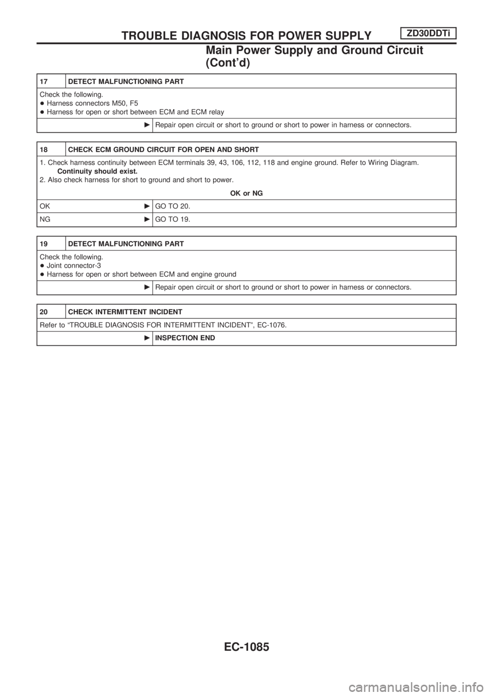
17 DETECT MALFUNCTIONING PART
Check the following.
+Harness connectors M50, F5
+Harness for open or short between ECM and ECM relay
cRepair open circuit or short to ground or short to power in harness or connectors.
18 CHECK ECM GROUND CIRCUIT FOR OPEN AND SHORT
1. Check harness continuity between ECM terminals 39, 43, 106, 112, 118 and engine ground. Refer to Wiring Diagram.
Continuity should exist.
2. Also check harness for short to ground and short to power.
OK or NG
OKcGO TO 20.
NGcGO TO 19.
19 DETECT MALFUNCTIONING PART
Check the following.
+Joint connector-3
+Harness for open or short between ECM and engine ground
cRepair open circuit or short to ground or short to power in harness or connectors.
20 CHECK INTERMITTENT INCIDENT
Refer to ªTROUBLE DIAGNOSIS FOR INTERMITTENT INCIDENTº, EC-1076.
cINSPECTION END
TROUBLE DIAGNOSIS FOR POWER SUPPLYZD30DDTi
Main Power Supply and Ground Circuit
(Cont'd)
EC-1085
Page 321 of 1033
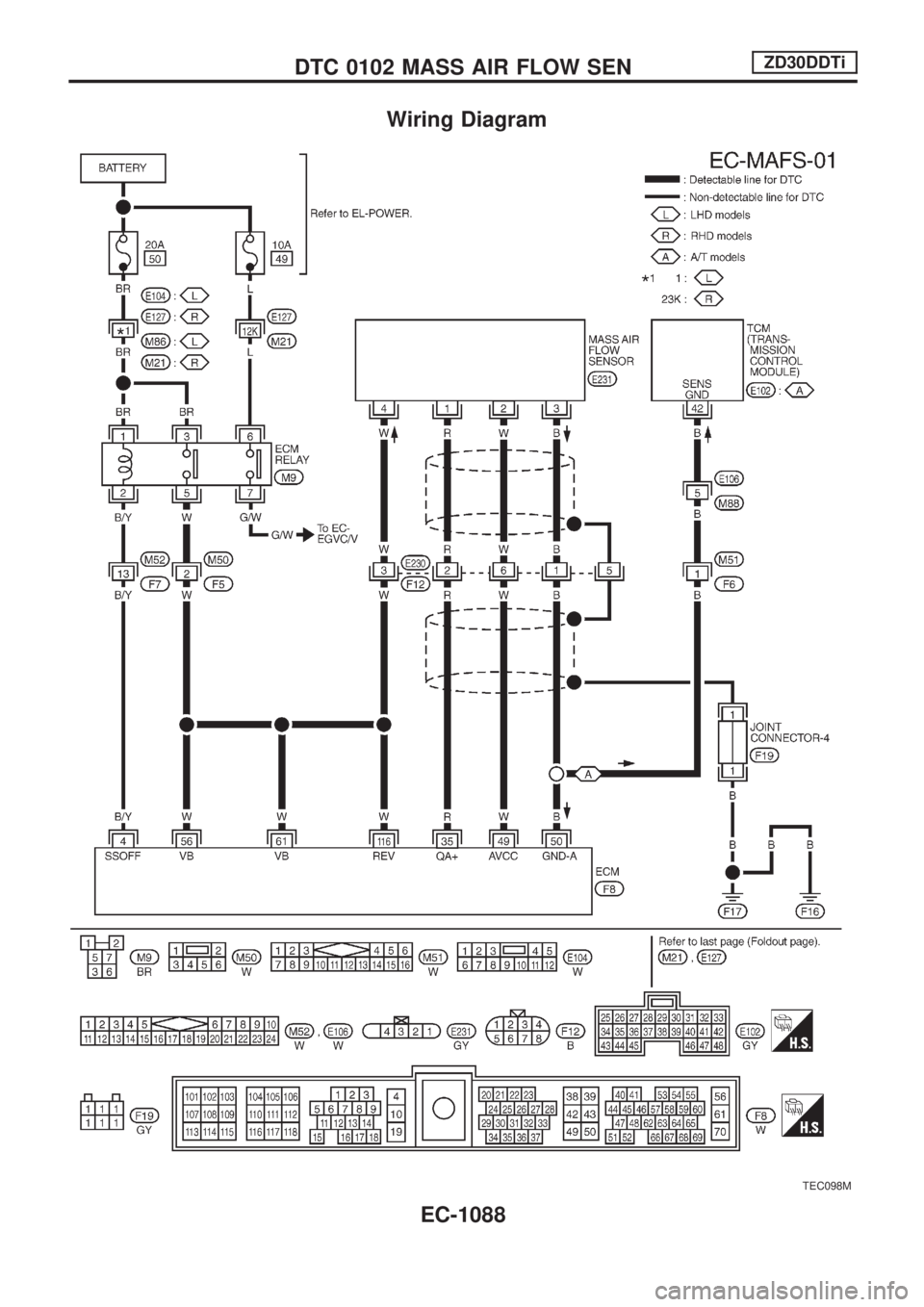
Wiring Diagram
TEC098M
DTC 0102 MASS AIR FLOW SENZD30DDTi
EC-1088
Page 323 of 1033
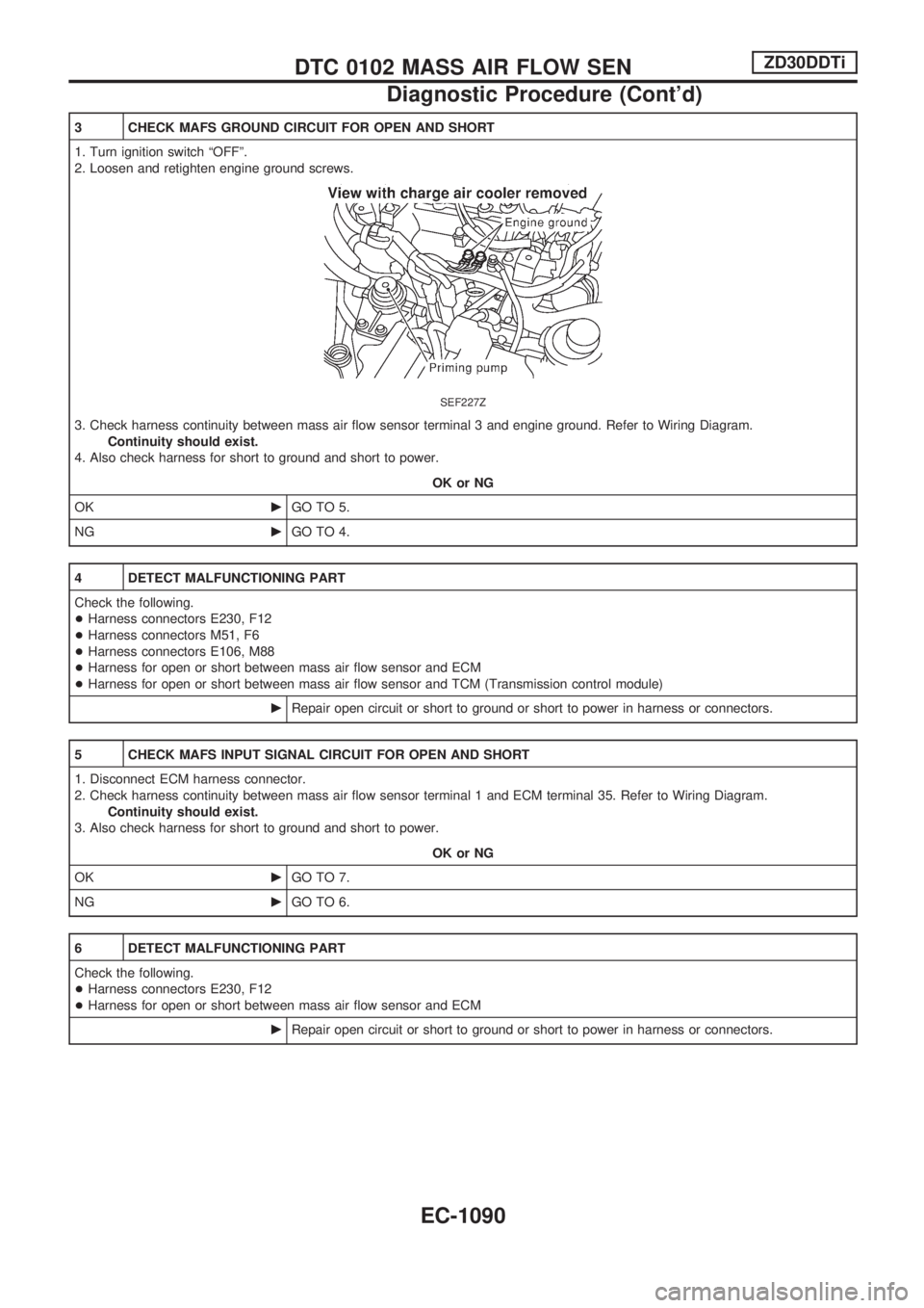
3 CHECK MAFS GROUND CIRCUIT FOR OPEN AND SHORT
1. Turn ignition switch ªOFFº.
2. Loosen and retighten engine ground screws.
SEF227Z
3. Check harness continuity between mass air flow sensor terminal 3 and engine ground. Refer to Wiring Diagram.
Continuity should exist.
4. Also check harness for short to ground and short to power.
OK or NG
OKcGO TO 5.
NGcGO TO 4.
4 DETECT MALFUNCTIONING PART
Check the following.
+Harness connectors E230, F12
+Harness connectors M51, F6
+Harness connectors E106, M88
+Harness for open or short between mass air flow sensor and ECM
+Harness for open or short between mass air flow sensor and TCM (Transmission control module)
cRepair open circuit or short to ground or short to power in harness or connectors.
5 CHECK MAFS INPUT SIGNAL CIRCUIT FOR OPEN AND SHORT
1. Disconnect ECM harness connector.
2. Check harness continuity between mass air flow sensor terminal 1 and ECM terminal 35. Refer to Wiring Diagram.
Continuity should exist.
3. Also check harness for short to ground and short to power.
OK or NG
OKcGO TO 7.
NGcGO TO 6.
6 DETECT MALFUNCTIONING PART
Check the following.
+Harness connectors E230, F12
+Harness for open or short between mass air flow sensor and ECM
cRepair open circuit or short to ground or short to power in harness or connectors.
DTC 0102 MASS AIR FLOW SENZD30DDTi
Diagnostic Procedure (Cont'd)
EC-1090
Page 326 of 1033
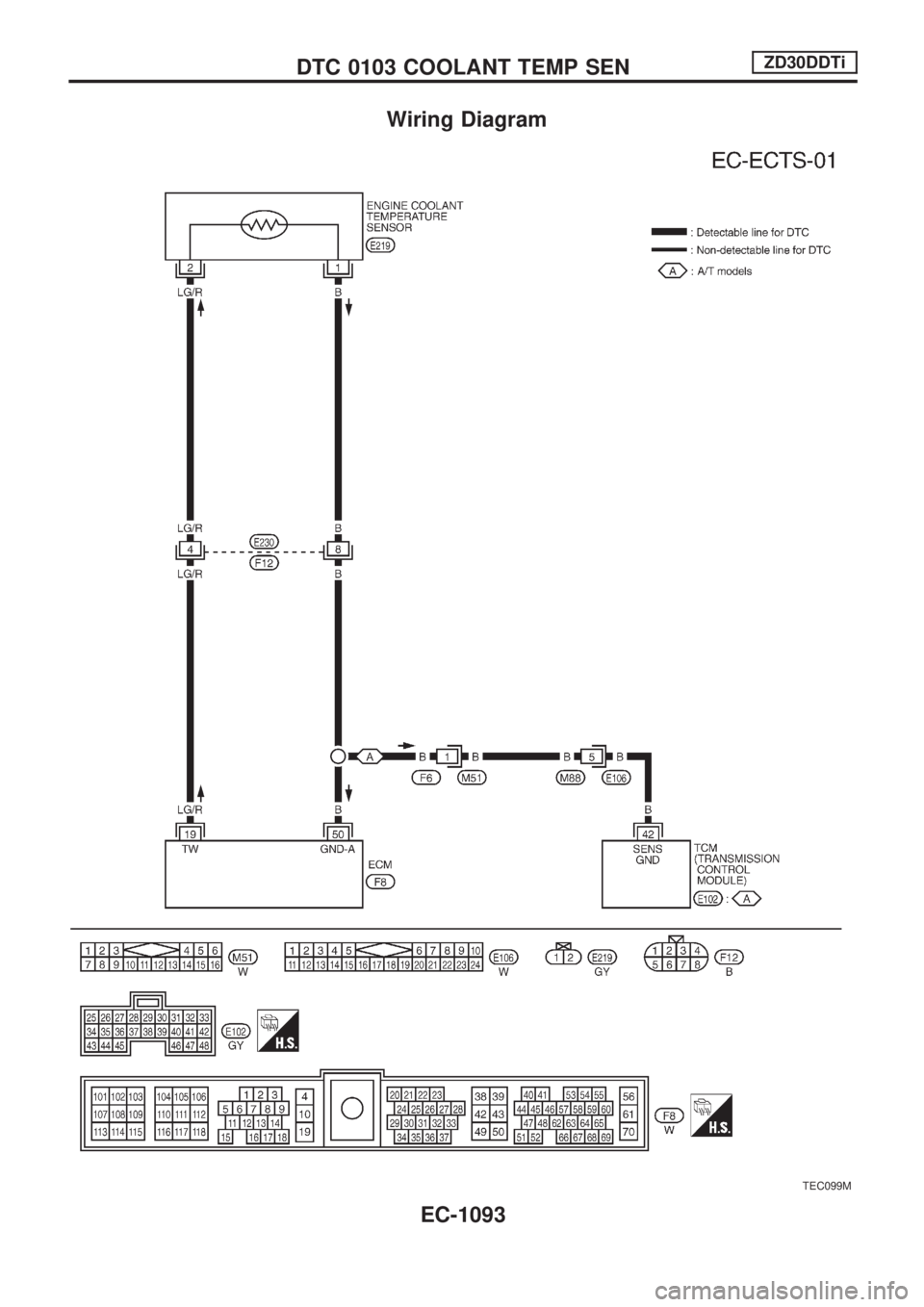
Wiring Diagram
TEC099M
DTC 0103 COOLANT TEMP SENZD30DDTi
EC-1093
Page 327 of 1033
Diagnostic Procedure
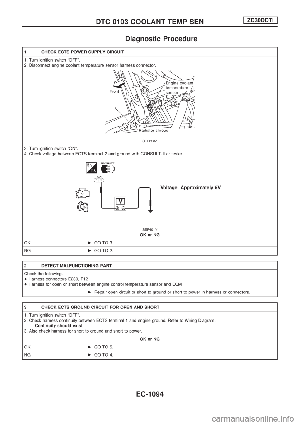
1 CHECK ECTS POWER SUPPLY CIRCUIT
1. Turn ignition switch ªOFFº.
2. Disconnect engine coolant temperature sensor harness connector.
SEF228Z
3. Turn ignition switch ªONº.
4. Check voltage between ECTS terminal 2 and ground with CONSULT-II or tester.
SEF401Y
OK or NG
OKcGO TO 3.
NGcGO TO 2.
2 DETECT MALFUNCTIONING PART
Check the following.
+Harness connectors E230, F12
+Harness for open or short between engine control temperature sensor and ECM
cRepair open circuit or short to ground or short to power in harness or connectors.
3 CHECK ECTS GROUND CIRCUIT FOR OPEN AND SHORT
1. Turn ignition switch ªOFFº.
2. Check harness continuity between ECTS terminal 1 and engine ground. Refer to Wiring Diagram.
Continuity should exist.
3. Also check harness for short to ground and short to power.
OK or NG
OKcGO TO 5.
NGcGO TO 4.
DTC 0103 COOLANT TEMP SENZD30DDTi
EC-1094
Page 331 of 1033
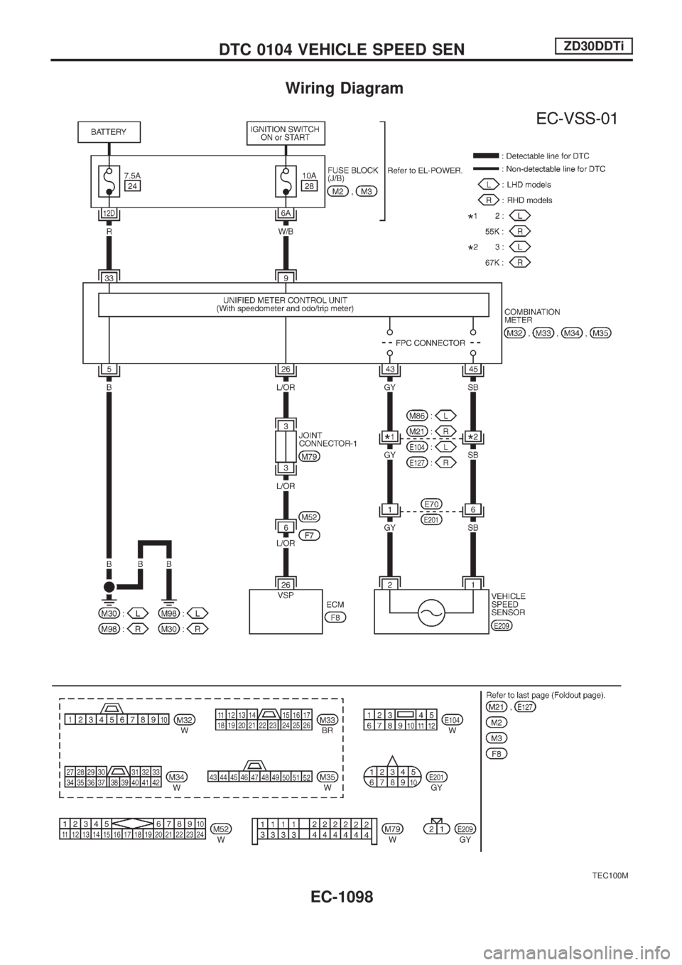
Wiring Diagram
TEC100M
DTC 0104 VEHICLE SPEED SENZD30DDTi
EC-1098
Page 332 of 1033
Diagnostic Procedure
1 CHECK VEHICLE SPEED SENSOR INPUT SIGNAL CIRCUIT FOR OPEN AND SHORT
1. Turn ignition switch ªOFFº.
2. Disconnect ECM harness connector and combination meter harness connector.
3. Check harness continuity between ECM terminal 26 and combination meter terminal 26. Refer to Wiring Diagram.
Continuity should exist.
4. Also check harness for short to ground and short to power.
OK or NG
OKcGO TO 3.
NGcGO TO 2.
2 DETECT MALFUNCTIONING PART
Check the following.
+Harness connectors M52, F7
+Joint connector-1
+Harness for open or short between ECM and combination meter
cRepair open circuit or short to ground or short to power in harness or connectors.
3 CHECK SPEEDOMETER FUNCTION
Make sure that speedometer functions properly.
OK or NG
OKcGO TO 5.
NGcGO TO 4.
4 CHECK SPEEDOMETER CIRCUIT FOR OPEN AND SHORT
Check the following.
+Harness connectors E70, E201
+Harness connectors M86, E104 or M21, E127
+Harness for open or short between combination meter and vehicle speed sensor
OK or NG
OKcCheck vehicle speed sensor and combination meter. Refer to EL section.
NGcRepair open circuit or short to ground or short to power in harness or connectors.
5 CHECK INTERMITTENT INCIDENT
Refer to ªTROUBLE DIAGNOSIS FOR INTERMITTENT INCIDENTº, EC-1076.
cINSPECTION END
DTC 0104 VEHICLE SPEED SENZD30DDTi
EC-1099
Page 335 of 1033
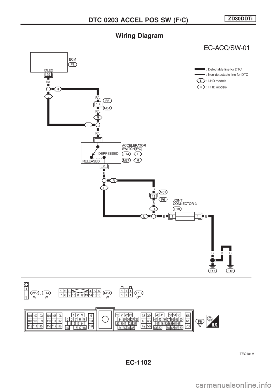
Wiring Diagram
TEC101M
DTC 0203 ACCEL POS SW (F/C)ZD30DDTi
EC-1102